Manufacturing process of composite cylinder sleeve

A manufacturing process and composite cylinder technology, applied in the manufacturing process of composite cylinder liners for hydraulic transmission cylinders, in the field of hydraulic transmission cylinders, can solve the problems of low hardness, rough surface wear, poor wear resistance, etc., and achieve high cost performance and high interface bonding strength , the effect of ensuring the uniformity of performance

Inactive Publication Date: 2012-05-30
KUNMING UNIV OF SCI & TECH
View PDF0 Cites 0 Cited by
  • Summary
  • Abstract
  • Description
  • Claims
  • Application Information

AI Technical Summary

Problems solved by technology

The piston rod makes frequent reciprocating linear motions in the oil cylinder. Once foreign matter such as lack of cooling lubricating oil or dust enters the cylinder, it will cause roughening on the surface of the cylinder liner and leakage of hydraulic oil, which will reduce the movement accuracy and force conversion efficiency of the oil cylinder. Even the oil cylinder is scrapped, resulting in the shutdown of the entire mechanical system
[0003] The cylinder liners currently used are basically medium-carbon quenched and tempered steel or alloy steel. Although the mechanical strength is high and can meet the strength requirements of the cylinder liner to withstand the pressure of hydraulic oil, the hardness is generally low and the wear resistance is poor. Once dust appears When sundries enter the oil cylinder or there is a lack of cooling lubricating oil, under the action of the piston rod, the surface will be worn and roughened.

Method used


Image

  • Manufacturing process of composite cylinder sleeve
  • Manufacturing process of composite cylinder sleeve
  • Manufacturing process of composite cylinder sleeve

Examples


Embodiment 1

[0029] Prepare hot rolling mill pinch roll oil cylinder liner, its procedure is as follows:

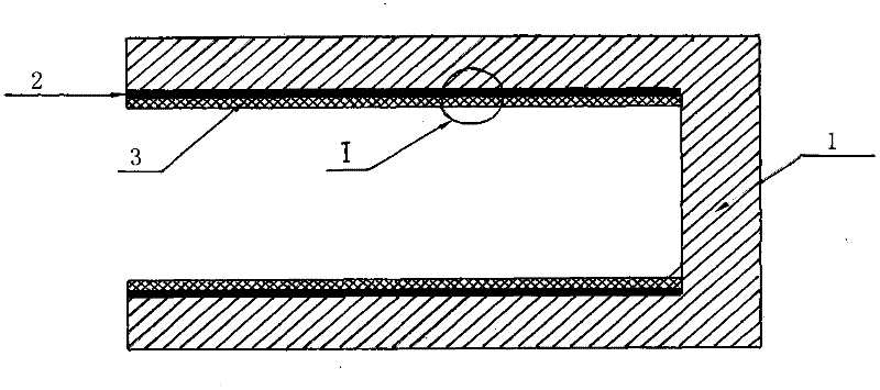
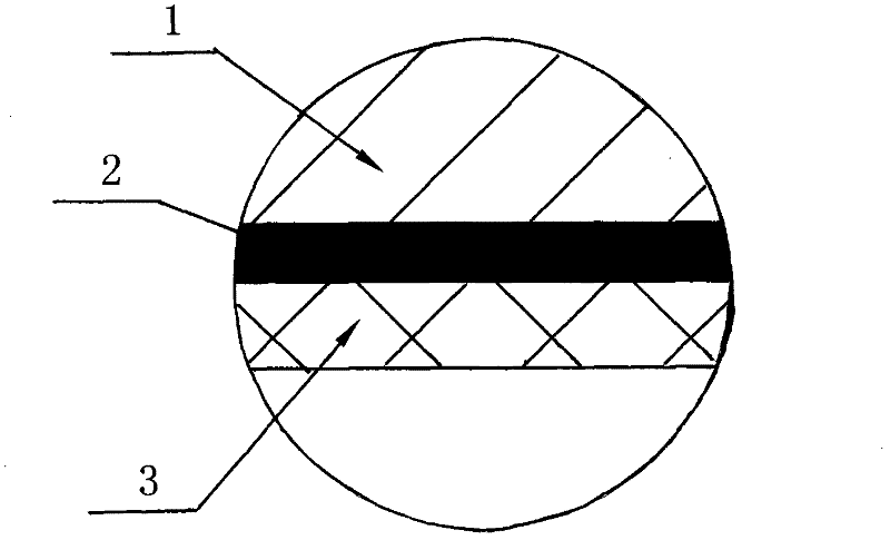
[0030] A. Medium carbon quenched and tempered steel hot rolling mill pinch roller cylinder liner blank 1 processed by conventional technology;

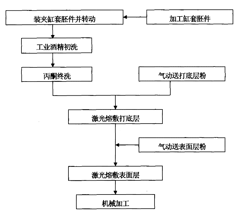
[0031] B. Install the jig on the cylinder liner blank 1, and turn the jig at a linear speed of 600mm / min;

[0032] C. Pour industrial alcohol on the working surface of the cylinder liner for preliminary cleaning, and then pour acetone for final cleaning;

[0033] D. Turn on the argon pneumatic powder feeding device to deliver 18-8 type austenitic stainless steel powder with a particle size of 100 mesh to the working surface of the cylinder liner;

[0034] E. Use a laser with a power of 3.5KW and a bandwidth of 3mm to irradiate the 18-8 type austenitic stainless steel powder to melt it, and deposit a layer 2 with a thickness of 2mm;

[0035] F. Argon gas pneumatically transports 1Cr13 martensitic stainless steel powder with a particle size o...

Embodiment 2

[0039] Prepare pinch roll cylinder liners for hot rolling mills.

[0040] The preparation is basically the same as in Example 1, except that the cylinder liner blank is made of alloy steel; the particle size of the 18-8 type austenitic stainless steel powder used in the process D is 200 mesh, and the thickness of the bottom layer is 200 mesh. The particle size of the 1Cr13 type martensitic stainless steel powder used in the operation F is 200 mesh, and the thickness of the surface layer is 4mm; other conditions are the same as in Example 1.

Embodiment 3

[0042] Prepare pinch roll cylinder liners for hot rolling mills.

[0043] The preparation is basically the same as in Example 1, except that the cylinder liner blank is made of alloy steel; the particle size of the 18-8 type austenitic stainless steel powder used in the process D is 300 mesh, and the thickness of the bottom layer is 300 mesh. 3mm; the particle size of the 1Cr13 type martensitic stainless steel powder used in the operation F is 300 mesh, and the thickness of the surface layer is 2mm; other conditions are the same as in Example 1.


PUM

PropertyMeasurementUnit
particle sizeaaaaaaaaaa
hardnessaaaaaaaaaa
particle sizeaaaaaaaaaa

Abstract

The invention discloses a manufacturing process of a composite cylinder sleeve. In the process, a layer of 18-8 type Austenitic stainless steel is firstly clad on a working surface of a medium carbon quenched and tempered steel or alloy steel cylinder sleeve to be used as a bond coat by a laser cladding technology, and then a layer of 1Cr13 type Martensitic stainless steel is clad to be used as awear-resistant corrosion-resistant surface layer to realize gradient compounding and strengthening, so the cylinder sleeve of a hydraulic transmission oil cylinder has longer service life and more balanced operation performance, and the problems of cylinder sleeve surface galling, hydraulic oil leakage and the like caused by the frequent reciprocating motion of a piston rod when the working surface of the cylinder sleeve lacks cooling lubricating oil or foreign matters enter the cylinder are avoided. The manufacturing process disclosed by the invention has strong technological parameter controllability, is convenient to operate, and brings convenience industrialized mass production.

Description

technical field [0001] The invention relates to a hydraulic transmission oil cylinder in the field of mechanical equipment, in particular to a manufacturing process of a composite cylinder sleeve of the hydraulic transmission oil cylinder. Background technique [0002] Because the oil cylinder is easy to change directions, it can conveniently realize overload protection, can automatically adjust the traction speed within a given range, and can realize stepless speed regulation and high degree of automation. It is widely used in the hydraulic transmission system of mechanical devices. It is the main component of the hydraulic transmission cylinder and also the pressure bearing part of the hydraulic oil in the hydraulic transmission cylinder. The piston rod makes frequent reciprocating linear motions in the oil cylinder. Once foreign matter such as lack of cooling lubricating oil or dust enters the cylinder, it will cause roughening on the surface of the cylinder liner and lea...

Claims


Application Information

Patent Timeline
Patent Type & Authority Patents(China)
IPC IPC(8): B23P15/00C23C24/10
Inventor 岑启宏蒋业华周荣范云鹰崔小英
Owner KUNMING UNIV OF SCI & TECH
Why Eureka
Try Eureka