Laser cladding reinforcing process of motor central spindle

A laser cladding and electric motor technology, applied in the field of mechanical equipment, can solve the problems of waste of spare parts, easy to be worn, corroded, and increase the loss cost, and achieve compact and fine solidification structure, ensure performance uniformity, and high interface bonding. the effect of strength

Inactive Publication Date: 2013-01-16
KUNMING UNIV OF SCI & TECH
View PDF0 Cites 0 Cited by
  • Summary
  • Abstract
  • Description
  • Claims
  • Application Information

AI Technical Summary

Problems solved by technology

Commonly used motor mandrels are made of medium-carbon steel after quenching and tempering heat treatment. Although medium-carbon quenched and tempered steel has the basic performance of bearing large torque and stress as a whole, its anti-wear and corrosion resistance is very poor. The position is most likely to be worn and corroded, so that the entire mandrel is scrapped and replaced, resulting in a large number of downtime for maintenance and waste of spare parts, increasing the cost of loss in the daily production of the enterprise

Method used


Image

  • Laser cladding reinforcing process of motor central spindle
  • Laser cladding reinforcing process of motor central spindle
  • Laser cladding reinforcing process of motor central spindle

Examples


Embodiment 1

[0028] To prepare the mandrel of a 55KW AC motor with local gradient composite strengthening, the specific procedure is as follows.

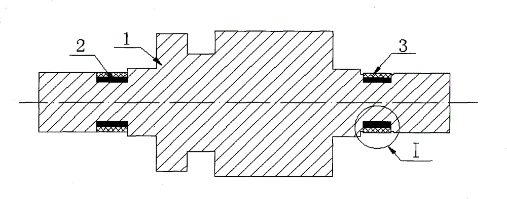
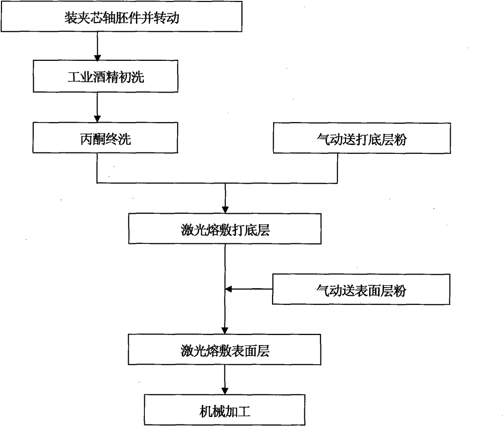
[0029] A. Install the motor core shaft blank (1) made of medium carbon quenched and tempered steel into the fixture, and rotate the fixture at a linear speed of 600mm / min;

[0030] B. Pour industrial alcohol on the bearing position of the mandrel for preliminary cleaning, and then pour acetone for final cleaning;

[0031] C. Turn on the argon pneumatic powder feeding device to deliver 18-8 austenitic stainless steel powder to the bearing position of the mandrel;

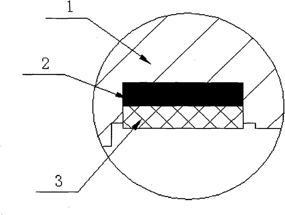
[0032] D. Irradiate the 18-8 type austenitic stainless powder with a power of 3.5KW and a bandwidth of 3mm to melt it, and deposit a layer with a thickness of 2mm (2);

[0033] E. Argon gas pneumatically transports 1Cr13 martensitic stainless steel powder to the bottom layer;

[0034] F, irradiating 1Cr13 type austenitic stainless steel powder with a power of 3.5KW and a bandwidth of...

Embodiment 2

[0037] Prepare pinch roll cylinder liners for hot rolling mills.

[0038] The preparation situation is basically the same as in Example 1, except that the particle size of the 18-8 type austenitic stainless steel powder used in the process C is 200 mesh, and the thickness of the bottom layer is 1 mm; the 1Cr13 type Martensitic stainless steel powder used in the process E The particle size of bulk stainless steel powder is 200 orders, and the thickness of surface layer is 4mm; All the other situations are identical with embodiment 1.

Embodiment 3

[0040] Prepare pinch roll cylinder liners for hot rolling mills.

[0041] The preparation situation is basically the same as in Example 1, except that the particle size of the 18-8 type austenitic stainless steel powder used in the process C is 300 mesh, and the thickness of the bottom layer is 3mm; the 1Cr13 type Martensitic stainless steel powder used in the process E The particle size of bulk stainless steel powder is 300 orders, and the thickness of surface layer is 2mm; All the other situations are identical with embodiment 1.


PUM

PropertyMeasurementUnit
particle sizeaaaaaaaaaa

Abstract

The invention discloses a laser cladding reinforcing process of a motor central spindle. In the reinforcing process, a layer of 18-8 type austenitic stainless steel serving as a base coat is cladded by laser cladding technology at the bearing position of the central spindle, and then a layer of 1Cr13 type martensite stainless steel serving as a wear-resistant and corrosion-resistant surface layeris cladded, so that stepped reinforcement is realized, the service life of the motor central spindle is prolonged, operating performance is balanced, and using problems such as corrosion of the central spindle at the bearing position, shaft deviation caused by wear, roughing of a bush and the like are solved. In the process, parameter controllability is high, machining operation is convenient andindustrial batch production is convenient.

Description

technical field [0001] The invention relates to a motor in the field of mechanical equipment, in particular to a local composite strengthening process for a motor mandrel. Background technique [0002] The motor mandrel is the main component of the motor rotor and also the main load-bearing part of the motor. The silicon steel sheet and coil winding as the core part of the motor are fixed on the mandrel, and the silicon steel sheet and coil winding drive the mandrel at a high speed under the action of the electromagnetic field. Rotation, the bearing position on both sides of the mandrel, that is, the bearing pad support position fixed on the motor housing, is subject to friction and high temperature for a long time, which is very easy to cause wear and corrosion of the mandrel. After the mandrel is worn and corroded, the diameter becomes smaller, and the gap with the bearing bush becomes larger, radial runout occurs during operation, and the whole motor emits a huge noise, w...

Claims


Application Information

Patent Timeline
Patent Type & Authority Patents(China)
IPC IPC(8): C23C24/10
Inventor 岑启宏范云鹰蒋业华周荣黎振华
Owner KUNMING UNIV OF SCI & TECH
Why Eureka
Try Eureka