Hoisting method of steel reinforcement cage

A technology for hoisting and reinforcing steel cages, which is used in transportation and packaging, load hanging components, sheet pile walls, etc., can solve problems such as insufficient guarantee of hoisting without deformation, insufficient rigidity of steel bars, and potential safety hazards, so as to save reinforcement. The effect of settlement time, high work efficiency, and not easy safety hazards

Active Publication Date: 2011-05-25
CHEM IND GEOTECHN ENG
View PDF5 Cites 37 Cited by
  • Summary
  • Abstract
  • Description
  • Claims
  • Application Information

AI Technical Summary

Problems solved by technology

This method is generally time-consuming and labor-intensive
[0005] (2) Reinforcement method: the design rigidity of the reinforcement cage is higher, and there is a triangular reinforcement in each reinforcement ring, but it is still not enough to ensure that the hoisting will not be deformed
This method is time-consuming and labor-intensive
[0006] (3) Double-hook lifting method: This method does not reinforce the steel cage, and uses a high-configuration crane and adds a spreader to complete the lifting of the steel cage. However, most of the lifting beams are welded with channel steel. Affected by the welding quality, use There will be cracking in the middle, and there will be safety hazards
[0008] However, a longer steel cage has a greater weight, and the steel bars connected by the hook are often not rigid enough to cause deformation. In this way, the lifting of the steel cage is more critical. Proper lifting can ensure that the steel cage does not deform, otherwise it will aggravate the reinforcement cage. Deformation due to stress during hoisting

Method used


Image

  • Hoisting method of steel reinforcement cage
  • Hoisting method of steel reinforcement cage
  • Hoisting method of steel reinforcement cage

Examples


Embodiment Construction

[0027] The present invention will be further described below in conjunction with the accompanying drawings and embodiments.

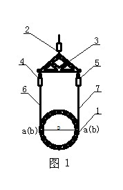
[0028] The reinforcing cage of the present embodiment has a diameter of 0.5m, a cage length of 33.6m, and a reinforcing cage of an aspect ratio of 67.2. No special reinforcement is required for the hoisting reinforcing cage, and it is placed flat on a platform on the ground. The hoisting device adopts a hoist (not shown) with main and auxiliary hoisting hooks and specially provided main hoisting assembly I and auxiliary hoisting assembly II.

[0029] The main lifting components such as figure 1 , mainly be made up of lifting beam 3 and two groups of lifting pulleys 4,5 spanning wire rope 6,7 on it, mention lifting beam 3 two ends and connect one group of lifting pulleys 4,5 respectively. The lifting beam 3 is an isosceles triangular steel member, which is cut from a single piece of steel plate, without a welded part, so as to ensure a stronger tensile ...


PUM


Abstract

The invention relates to a hoisting method of a steel reinforcement cage. The method comprises the following steps of: 1) preparing for hoisting, namely preparing a hoisting machine which is provided with a main hoisting hook and an auxiliary hoisting hook and manufacturing a main hoisting component, an auxiliary hoisting component and the like; 2) setting hoisting points, namely setting main hoisting points at the two ends of the horizontal diameter of a horizontal steel reinforcement cage and setting an auxiliary hoisting point on a steel reinforcement cage at the upper end of the vertical diameter of the horizontal steel reinforcement cage, and connecting the main and auxiliary hoisting components with corresponding main and auxiliary hoisting points; and 3) hoisting, namely hoisting the main and auxiliary hoisting hooks at the same time, always keeping the distance of between 0.5 and 1.0 meter between the steel reinforcement cage and the ground by using the auxiliary hoisting hookafter the steel reinforcement cage leaves the ground, continually hoisting the main hoisting hook upwards, gradually erecting the steel reinforcement cage until the steel reinforcement cage is vertical to the ground, rotating the hoisting machine, aligning the steel reinforcement cage with a drill hole and putting the steel reinforcement cage into the drill hole. The hoisting method has the advantages that: the steel reinforcement cage is not deformed easily, reinforcement is not required during hoisting and working efficiency is high; construction cost is low; and design intensity of the steel reinforcement cage is ensured, potential safety hazard is not left easily and construction quality is ensured.

Description

[0001] technical field [0002] The invention relates to hoisting in construction projects such as buildings, railways and highways, in particular to a method for hoisting a steel cage. Background technique [0003] Reinforced concrete bored piles are widely used in industrial and civil buildings, railways and highways and other construction fields. It is a very important link in the construction of bored piles to lower the reinforcement cage into the borehole. Due to the unreasonable lifting method, the reinforcement cage Generally, the rigidity is insufficient and it is easy to deform. There are several methods of lifting reinforcement cages commonly used in pile foundation construction: [0004] ⑴, wood or steel pipe reinforcement method: generally not more than 20 meters. When it exceeds 20 meters, it is necessary to consider the production and installation of sections. When lowering, first use wire cutters to cut the iron wires that can be cut to bind the wood or...

Claims


Application Information

Patent Timeline
Patent Type & Authority Applications(China)
IPC IPC(8): B66C1/12E02D5/34
Inventor 尤苏南
Owner CHEM IND GEOTECHN ENG
Why Eureka
Try Eureka