Digital pileup waveform processing method and system

A waveform processing and waveform technology, which is applied in the high-energy particle detection data acquisition system, digital accumulation waveform processing method and its system field, can solve the problem of inability to judge whether it contains scintillation pulse waveform, cannot be used to establish a real-time pileup processing system, noise The impact of the problem, to achieve the effect of increasing the counting rate, reducing data loss, and improving the signal-to-noise ratio

Active Publication Date: 2011-05-25
HUAZHONG UNIV OF SCI & TECH +1
View PDF5 Cites 33 Cited by
  • Summary
  • Abstract
  • Description
  • Claims
  • Application Information

AI Technical Summary

Problems solved by technology

Secondly, the judgment of the pileup waveform and the segmentation of the waveform by this method are based on the maximum value of the pulse derivative of the entire frame, which will lead to two main problems: (1) This method cannot judge whether each frame of digital file contains flicker pulses Therefore, before the algorithm is processed, it is necessary to ensure that each digital file is a digital waveform containing a scintillation pulse; (2) when the amplitude of the scintillation pulse is small, this method is very susceptible to the influence of noise on the falling edge of the pulse, and will The normal digital flicker pulse waveform is judged as a pileup waveform, so this method has obvious defects in recovering the pulse position information (the acquisition of the position information is to divide a normal amplitude flicker pulse into four different sizes through a resistor network. Scintillation pulses, obtained by comparing the amplitude (energy) ratio between them, so the amplitudes of these four pulses are all small)
Due to the existence of the above defects, this method cannot be used to establish a real-time pileup processing system

Method used


Image

  • Digital pileup waveform processing method and system
  • Digital pileup waveform processing method and system
  • Digital pileup waveform processing method and system

Examples


example

[0094] A pileup waveform processing method and its system proposed by the present invention involve several parameters, which need to be adjusted for specific processing data to achieve good performance. Here are the parameters for processing data in this application example:

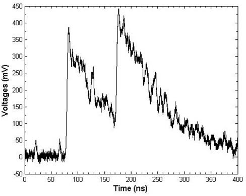
[0095] The digital pulse imported in step (1.1) is the scintillation pulse collected by using LYSO crystal and Hamamtsu R9800 PMT, and the typical waveform is Figure 5 shown. The sampling rate is 10GSps, the energy is 511KeV high-energy photons generate a pulse with an average peak value of about 300mV, an average pulse rise time of about 2ns, and a detector decay time constant of 47ns.

[0096] Step (1.2) adopts mean filtering, and the filter window size is 100;

[0097] Step (1.3) adopts backward derivation, derivation step size step=50;

[0098] Step (1.4) judges the rising edge area, threshold Threshold=0.0002;

[0099] Step (1.5) judges whether digital pulse waveform is pileup waveform, settin...


PUM


Abstract

The invention discloses a digital pileup waveform processing method and a digital pileup waveform processing system. The method comprises the following steps of: determining a pulse rising edge area, and judging whether a pulse has a pileup waveform or not according to a time interval between adjacent pulse rising edges; and dividing a digital waveform determined as pileup according to the risingedge and the falling edge of the pulse, reconstructing single event pulse waveforms in turn by using the divided waveform, and extracting single pulse information from the reconstructed waveforms. The invention also discloses the pileup waveform processing system, which comprises a pileup waveform discrimination module, a pulse waveform division module and a pulse waveform reconstruction module. By the method and the system, the pileup pulse waveform can be effectively discriminated, each single event pulse waveform in the pileup is accurately reconstructed, information such as energy, time, amplitude, decay time constant, position and the like of the single event pulse is accurately recovered, and the counting rate of a system under high activity, and the signal-to-noise ratio of a measuring result are improved.

Description

technical field [0001] The invention belongs to the fields of high-energy particle detection signal processing and digital signal processing, and in particular relates to a digital pileup waveform processing method and system thereof, which can be applied to a high-energy particle detection data acquisition system. Background technique [0002] In most fields of high-energy particle detection, as well as computed tomography (Computed Tomography, hereinafter referred to as CT), positron emission tomography (hereinafter referred to as PET), single photon emission computed tomography (Single Photon Emission Computed Tomography, In the field of medical imaging such as SPECT), the scintillation pulse signals collected and processed by the data acquisition system are converted from high-energy particles (such as γ-rays, X-rays, etc.) electrical signal. [0003] When multiple high-energy particles are captured by the same detector in a short period of time, the signals of multiple...

Claims


Application Information

Patent Timeline
Patent Type & Authority Applications(China)
IPC IPC(8): G01T1/202
CPCH03K5/125
Inventor 王希谢庆国陈源宝刘晶晶
Owner HUAZHONG UNIV OF SCI & TECH
Why Eureka
Try Eureka