Electronic tag antenna used in UHF (ultra high frequency) range and mobile phone using same

An electronic tag and antenna technology, applied in the field of UHF frequency band electronic tag antenna and mobile phones using the antenna, can solve the problems of complex structure of dipole antenna, inconvenient adjustment of impedance matching, and narrow matching bandwidth, etc., to enhance design flexibility, Save motherboard space and match the effect of bandwidth

Active Publication Date: 2011-05-25
成武县启源国有资产运营有限责任公司
View PDF3 Cites 4 Cited by
  • Summary
  • Abstract
  • Description
  • Claims
  • Application Information

AI Technical Summary

Problems solved by technology

[0005] In order to meet the requirements of different national standards for the bandwidth of electronic tags, there is a dipole antenna in the prior art, which can realize dual-frequency resonance at 867MHz and 915MHz. However, in addition to the antenna matching circuit, this electronic tag antenna needs additional Even so, there is still a difference between the resonant frequency and the matching frequency, resulting in a narrow impedance bandwidth
It can be seen that the structure of this kind of dipole antenna is relatively complicated, the impedance matching adjustment is inconvenient, and the matching bandwidth is narrow

Method used


Image

  • Electronic tag antenna used in UHF (ultra high frequency) range and mobile phone using same
  • Electronic tag antenna used in UHF (ultra high frequency) range and mobile phone using same
  • Electronic tag antenna used in UHF (ultra high frequency) range and mobile phone using same

Examples


Embodiment Construction

[0017] Below, the present invention will be described in detail with reference to the accompanying drawings.

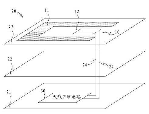
[0018] Such as figure 1 , figure 2 As shown, this embodiment provides an electronic tag antenna 10 for UHF frequency band, and a mobile phone 20 using the electronic tag antenna.

[0019] Among them, the electronic tag antenna 10 includes: a U-shaped radiation body 11 and a coupling loop 12 placed in the U-shaped ring of the radiation body 11 to couple with the radiation body 11 . The coupling loop is provided with two terminals connected to the antenna matching circuit 30 .

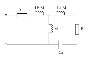
[0020] according to figure 1 The equivalent circuit of the shown electronic tag antenna 10 at the resonant frequency shows that at the resonant frequency , the real part of the input impedance of the electronic tag antenna for: , imaginary part for: ,in, is the resonant frequency of the antenna, , is the radiation resistance of the radiating body at the resonant frequency, i...


PUM


Abstract

The invention provides an electronic tag antenna used in an UHF (ultra high frequency) range and a mobile phone using the same. The antenna comprises a U-shaped radiating main body and a coupling ring, wherein, the coupling ring is equipped with two terminals connected with an antenna matching circuit; and the mobile phone comprises the electronic tag antenna, a main PCB (printed circuit board) of the mobile phone and the antenna matching circuit. In the invention, the real part and imaginary part of input impedance of the electronic tag antenna at the resonant frequency position are not related to parameters of the antenna matching circuit, and the real part and the imaginary part can be solely adjusted, thus achieving the effect of direct impedance matching between the electronic tag antenna and different antenna matching circuits. The electronic tag antenna has the advantages of simple structure and wide matching bandwidth, and is convenient in impedance matching adjustment; and meanwhile by utilizing the antenna in the mobile phone, the space of the main PCB of the mobile phone is saved, the manufacture cost of the mobile phone is effectively lowered, and the design flexibility of the mobile phone is enhanced.

Description

technical field [0001] The invention relates to the technical field of wireless mobile communication, in particular to a UHF frequency band electronic tag antenna and a mobile phone using the antenna. Background technique [0002] Radio frequency identification technology is an automatic identification technology that has emerged in recent years. The radio frequency identification system consists of a code reading system and an electronic label system. Among them, the electronic label system is divided into three types: active electronic label, semi-active electronic label and passive electronic label. [0003] UHF (Ultra High Frequency, Ultra High Frequency) frequency band electronic tag is a kind of passive electronic tag. Within the coverage of the signal transmitted by the code reading system, the UHK frequency band electronic tag extracts its work from the radio frequency energy emitted by the electronic tag antenna in the code reading system. The required power supply...

Claims


Application Information

Patent Timeline
Patent Type & Authority Applications(China)
IPC IPC(8): H01Q1/24H01Q1/36H04M1/02
Inventor 张莲罗敏丽
Owner 成武县启源国有资产运营有限责任公司
Why Eureka
Try Eureka