Flywheel energy storing device with permanent magnet bearing and thrust bearing

A permanent magnet bearing and flywheel energy storage technology, applied in the direction of bearings, electromechanical devices, bearing unloading, etc., can solve problems such as large vibration and instability, and achieve the effects of low friction loss, simple structure and good dynamic characteristics

Inactive Publication Date: 2011-06-01
SOUTHEAST UNIV
View PDF7 Cites 25 Cited by
  • Summary
  • Abstract
  • Description
  • Claims
  • Application Information

AI Technical Summary

Problems solved by technology

There is also an inherent technical defect in the vertical permanent magnetic suspension bearing and pivot jewel bearing flywhee

Method used


Image

  • Flywheel energy storing device with permanent magnet bearing and thrust bearing
  • Flywheel energy storing device with permanent magnet bearing and thrust bearing
  • Flywheel energy storing device with permanent magnet bearing and thrust bearing

Examples


Embodiment Construction

[0017] The technical solution of the present invention will be described in detail below in conjunction with the accompanying drawings.

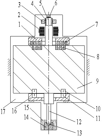
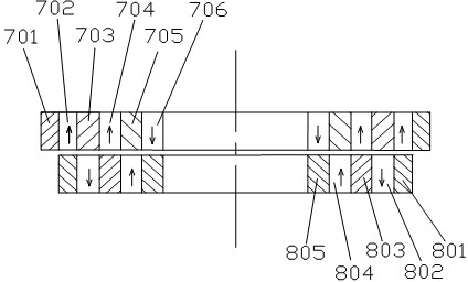
[0018] Such as figure 1 and figure 2As shown, a flywheel energy storage device with a permanent magnetic bearing and a thrust bearing of the present invention includes an upper shaft 5, a lower shaft 12, a flywheel body 9, and a permanent magnet composed of an upper magnetic ring 10 and a lower magnetic ring 11. Bearing, motor 2, bearing housing 14, damper and container 17 formed by frame. The upper shaft 5, the lower shaft 12, the flywheel body 9, the permanent magnetic bearing, the motor 2, the bearing seat 14, and the damper 14 are located in the container 17. Container 17 is preferably a vacuum-tight container. This can reduce the wind loss of the flywheel energy storage device during operation. The flywheel body 9 is made of metal. The flywheel body 9 is made of metal, which has the advantages of low cost, high inertia per unit v...


PUM


Abstract

The invention discloses a flywheel energy storing device with a permanent magnet bearing and a thrust bearing which comprises an upper shaft, a lower shaft, a flywheel body, a permanent magnet bearing, a motor, a bearing seat, a damper and a container, wherein the bottom of the lower shaft is provided with a ball head; the ball head is positioned in a groove at the top of the bearing; a damper stator is embedded in a ring groove of an upper soft magnetic ring; a damper rotor is embedded in a ring groove at the upper part of the flywheel body, and the upper end surface of a rotor outer insulative magnetic ring is opposite to the lower end surface of a stator outer permanent magnetic ring; the upper end surface of a rotor outer permanent magnetic ring is opposite to the lower end surface of a stator middle insulative magnetic ring; the upper end surface of a rotor middle insulative magnetic ring is opposite to the lower end surface of a stator middle permanent magnetic ring; the upper end surface of the rotor inner permanent magnetic ring is opposite to the lower end surface of a stator inner permanent magnetic ring; and the upper end surface of the rotor inner permanent magnetic ring is opposite to the low end surface of the stator inner permanent magnetic ring. According to the flywheel energy storing device of the structure, the flywheel body can pass through the low order critical speed of rotation, and the whole flywheel energy storing device has favorable dynamic characteristics.

Description

technical field [0001] The invention belongs to the technical field of electric energy conversion and storage, and in particular relates to a flywheel energy storage device with a permanent magnetic bearing and a thrust bearing. Background technique [0002] The flywheel energy storage device has outstanding advantages such as high power conversion efficiency, fast charging and discharging, no geographical environment restrictions, no pollution to the environment, and high energy storage density per unit mass. It can be used for power peak regulation, electric vehicle flywheel batteries, and uninterrupted power supply. , electromagnetic guns, electrochemical guns and high-power welding machines and other fields. At present, flywheel technology is developing in the direction of high speed and high power. Vertical permanent magnetic suspension bearings and pivot jewel bearing flywheel energy storage devices are a class of classic structures that have attracted much attention ...

Claims


Application Information

Patent Timeline
IPC IPC(8): H02K7/02H02K7/09H02K5/16F16C32/04F16F15/18H02K1/27H02K1/02
CPCY02E60/16F16C39/066F16C2361/55
Inventor 蒋书运王洪昌
Owner SOUTHEAST UNIV
Why Eureka
Try Eureka