Combined sewage treatment method for oil field

A sewage treatment method and combined technology, applied in the directions of water/sewage multi-stage treatment, water/sludge/sewage treatment, chemical instruments and methods, etc., can solve the problem of difficult to realize the combined structure and quick installation of sewage treatment equipment, Increase the effect and speed of sedimentation and flocculation of suspended solids, high investment, infrastructure and operation and maintenance costs, and achieve the effects of shortening the construction period, less conversion and connection of pipe networks, and less overall investment and operating costs

Active Publication Date: 2011-06-15
BC P INC CHINA NAT PETROLEUM CORP +1
View PDF4 Cites 7 Cited by
  • Summary
  • Abstract
  • Description
  • Claims
  • Application Information

AI Technical Summary

Problems solved by technology

The disadvantage is that in the process of magnetic separation, while adding "magnetic carrier", it is still necessary to add a certain proportion of flocculant (PAC) and polyacrylamide (PAM) chemicals to increase the sedimentation and flocculation effect of suspended solids in sewage and speed
Due to the large number of units, it is difficult to realize the combined structure and quick installation of sewage treatment equipment
[0016] There are problems in the traditional oilfield produced water treatment process, that is, the process takes a long time, the equipment occupies a large area, and the investment, infrastructure and operation and maintenance costs are high
A large amount of chemical agents are added, and the generated sludge causes environmental problems

Method used


Image

  • Combined sewage treatment method for oil field
  • Combined sewage treatment method for oil field
  • Combined sewage treatment method for oil field

Examples


Embodiment 1

[0037] Embodiment 1: The following is a detailed description of the steps of the combined oilfield sewage treatment method of the present invention in conjunction with the accompanying drawings.

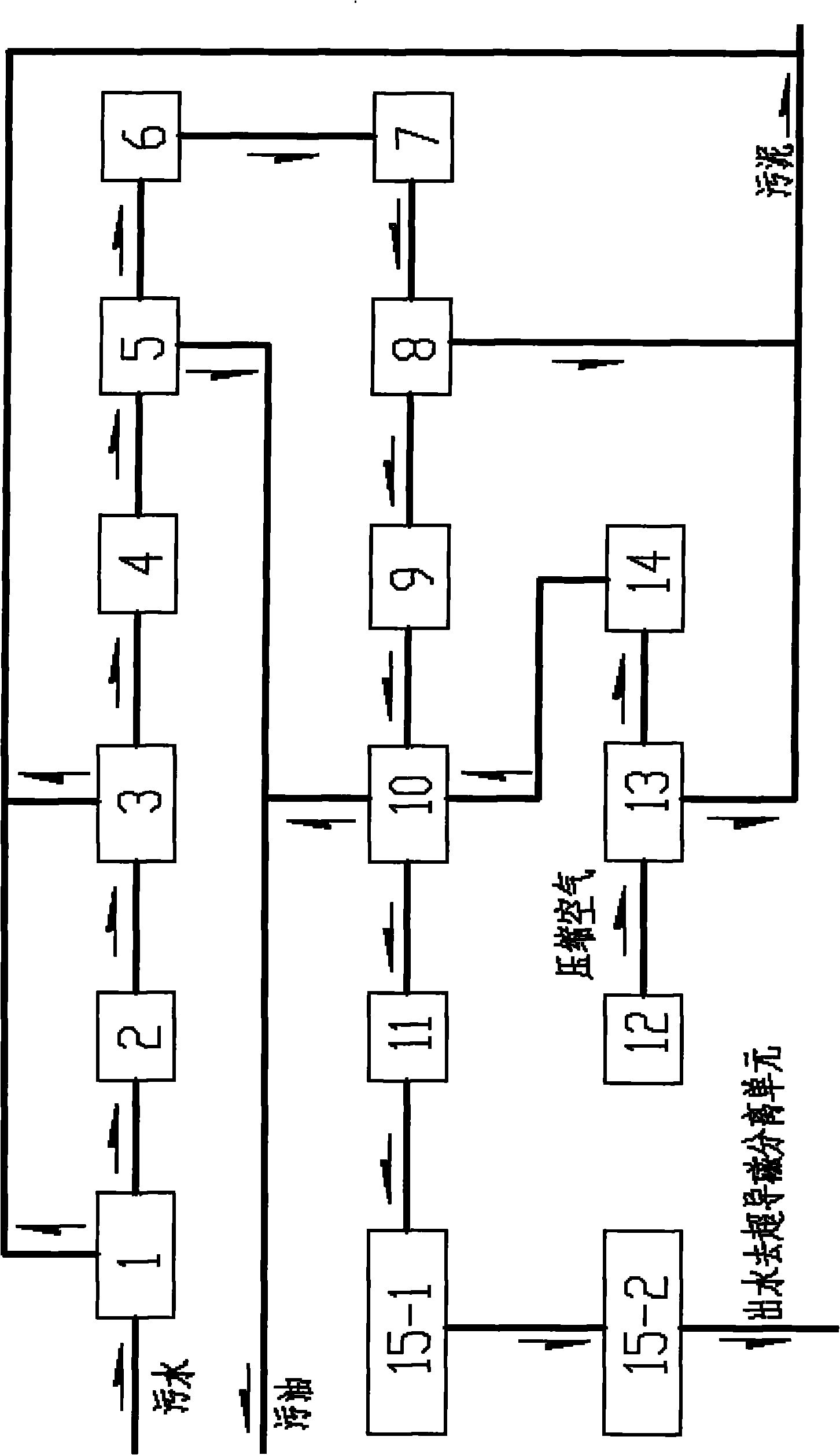
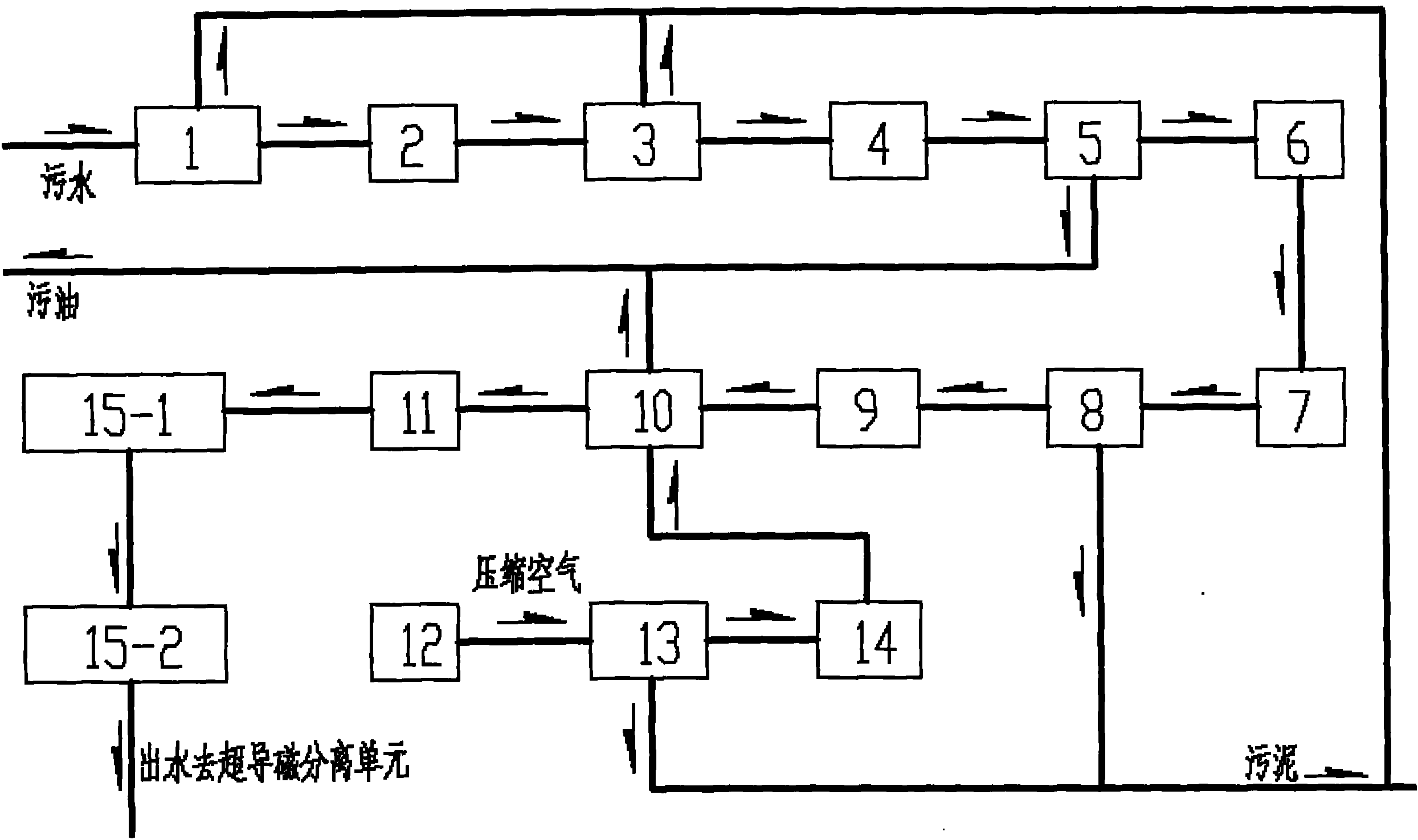
[0038] refer to figure 1 . The "swirl flow pretreatment oil removal unit" of the present invention is the separation method of oil removal and coarse suspended solids removal:

[0039] The produced water to be treated first enters the coarse filter 1, and the coarse filter 1 removes part of the sludge; the produced water discharged from the coarse filter 1 enters the pressure regulating device 2 for pressure regulation, and the water pressure condition is greater than 0.4MPa. If the pressure is too high, decompress in two stages to stabilize the pressure in the range of 0.4-0.6MPa. The pressure is stable, and it is sent to the pre-metering filter 3 for filtration. The pre-metering filter 3 filters out part of the sludge, and the water filtered by the pre-metering filter 3 enters th...


PUM

PropertyMeasurementUnit
particle diameteraaaaaaaaaa

Abstract

The invention discloses a combined sewage treatment method for an oil field, which is applied to sewage treatment in a petroleum development gather and delivery process. The method comprises the following steps of: (A) performing a physical separation method: roughly filtering the effluent, regulating the pressure, filtering before metering, and metering the flow to stabilize the pressure; feeding the sewage into a hydraulic cyclone to separate floating oil and dispersible oil; feeding the sewage into a normal pressure buffer tank, and feeding the sewage into the inflating hydraulic cyclone by compression of a screw pump to remove emulsified oil in the sewage; (B) filtering the water flowing out from the inflating hydraulic cyclone into a laminated filter; and (C) feeding the water flowing out from the laminated filter into a magnetic seed mixing tank of a superconducting magnetic separation unit, feeding the nano magnetic seeds into the magnetic seed mixing tank through a magnetic seed feeding tank, pressurizing the water and the magnetic seeds through a mixing pump to enter a pre-sedimentation tank to form lump sediment using the magnetic seeds as cores, feeding the upper clarified liquid and partial water containing the magnetic seed lumps into a superconducting magnetic separation device, and feeding the separated magnetic seeds into the magnetic seed feeding tank. The method has the advantages of no need of chemical agents, short process flow, small floor area and low integral investment and running expenses.

Description

technical field [0001] The invention relates to an oil field sewage treatment process technology, in particular to a combined oil field sewage treatment process, which is used for the sewage treatment in the oil development gathering and transportation process. Background technique [0002] At present, the most widely used produced water treatment method in oilfields is the traditional process based on "coagulation-sedimentation-filtration", supplemented by scale inhibition, corrosion inhibition, sterilization or biochemical, adsorption, membrane separation treatment, etc. The existing technological process is relatively mature, adaptable, stable and reliable, but the equipment used in this technological process occupies a large area, high energy consumption and high investment costs. [0003] The main control indicators of oilfield produced water treatment process are oil content, suspended solids content and median particle size of suspended solids. [0004] The state of ...

Claims


Application Information

Patent Timeline
Patent Type & Authority Applications(China)
IPC IPC(8): C02F9/12
Inventor 王秀文智玉杰
Owner BC P INC CHINA NAT PETROLEUM CORP
Why Eureka
Try Eureka