Single-stage boost inverter

An inverter, single-stage technology, applied in the field of new energy power generation inverter, can solve the problems of reducing conversion efficiency, increasing system cost, and devices cannot be turned on at the same time

Inactive Publication Date: 2011-06-22
NANJING UNIV OF AERONAUTICS & ASTRONAUTICS
View PDF4 Cites 13 Cited by
  • Summary
  • Abstract
  • Description
  • Claims
  • Application Information

AI Technical Summary

Problems solved by technology

For DC/AC power conversion applications with low DC voltage and higher AC output voltage, an additional DC/DC boost converter is required. This additional power conversion stage increases the cost of the system and reduces the conversion efficiency.
[0005] (3) The upper and lower devices of each bridge arm cannot be turned on at the same time, whether it is inten...

Method used


Image

  • Single-stage boost inverter
  • Single-stage boost inverter
  • Single-stage boost inverter

Examples


Embodiment Construction

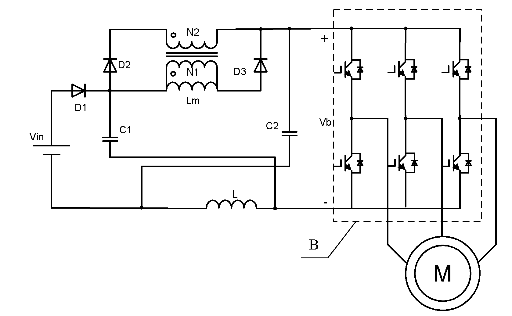
[0023] as attached image 3 As shown, the single-stage boost inverter topology of the present invention adds a boost network composed of passive devices before the three-phase switching bridge B of the traditional voltage-type inverter: a primary and secondary windings are tightly coupled and N1


PUM


Abstract

The invention discloses a single-stage boost inverter, which comprises a coupling inductor of which a primary secondary-side winding is tightly coupled and N1 is smaller than N2; one end of an excitation inductor is connected with the cathode of a first diode, the anode of a second diode, and one end of a first capacitor, and the other end of the first capacitor is connected with the anode of a third diode; the anode of the first diode is connected with the anode of a power supply; the cathode of the second diode is connected to one end of a secondary-side winding of the coupling inductor; the other end of the secondary-side winding is connected with the cathode of the third diode and the direct current (DC) bus positive terminal of an inverter; one end of a second capacitor is connected with the DC bus positive terminal, and the other end of the second capacitor is connected with the cathode of the power supply; the other end of the first capacitor is connected with the DC bus negative terminal of the inverter and one end of the inductor, while the other end of the inductor is connected with the cathode of the power supply. By employing a shoot-through zero vector which is not allowed by a conventional inverter by the invention, the DC bus voltage of the inverter is boosted, the deficiency of a conventional voltage inverter is overcome, and the inverter is free from shoot-through phenomenon caused by electromagnetic interference, and is not needed to be inserted into a dead area.

Description

technical field [0001] The invention relates to a single-stage step-up inverter, which is especially suitable for a motor drive system in which a DC bus needs to be powered by a low-voltage step-up and a new energy power generation inverter adapting to a relatively large input voltage range. Background technique [0002] The traditional voltage source inverter inputs DC voltage and outputs AC voltage, and has a wide range of applications. The input DC voltage of the voltage source inverter can be obtained from the power grid or the rotating AC motor through rectification and filtering, and can also be obtained from batteries, fuel cells or photovoltaic cells, corresponding to general industrial applications (such as frequency converters), electric vehicles, renewable energy Distributed power generation and other occasions. In the voltage source inverter, due to the input DC voltage, the power semiconductor device is always kept forward biased, so the self-controlled forward...

Claims


Application Information

Patent Timeline
IPC IPC(8): H02M7/521
Inventor 周玉斐黄文新
Owner NANJING UNIV OF AERONAUTICS & ASTRONAUTICS
Why Eureka
Try Eureka