Method and equipment for manufacturing surfacing composite wear-resistant steel plate

A technology of wear-resistant steel plate and manufacturing method, which is applied in the direction of welding equipment, welding equipment, arc welding equipment, etc., and can solve the problems of limiting the production size of wear-resistant steel plate, uneven hardness and deformation of wear-resistant steel plate

Active Publication Date: 2011-06-29
CHANGZHOU FUTONG WELDING
View PDF6 Cites 38 Cited by
  • Summary
  • Abstract
  • Description
  • Claims
  • Application Information

AI Technical Summary

Problems solved by technology

[0007] Both of the above two welding methods have the following defects: (1) Welding unevenness caused by deformation of the steel plate: the steel plate will be deformed to a certain extent due to heating during the welding process, so that there will be a gap between the contact tip of the welding torch and the steel plate during the continuous welding process. The distance is constantly changing
This deformation will change the welding profile and molten pool depth, resulting in hardness non-uniformity and welding defects in wear-resistant steel plates
(2) Limitation of steel plate size: domestic we

Method used


Image

  • Method and equipment for manufacturing surfacing composite wear-resistant steel plate
  • Method and equipment for manufacturing surfacing composite wear-resistant steel plate
  • Method and equipment for manufacturing surfacing composite wear-resistant steel plate

Examples


Embodiment 1

[0051] (Example 1, equipment for manufacturing surfacing composite wear-resistant steel plates)

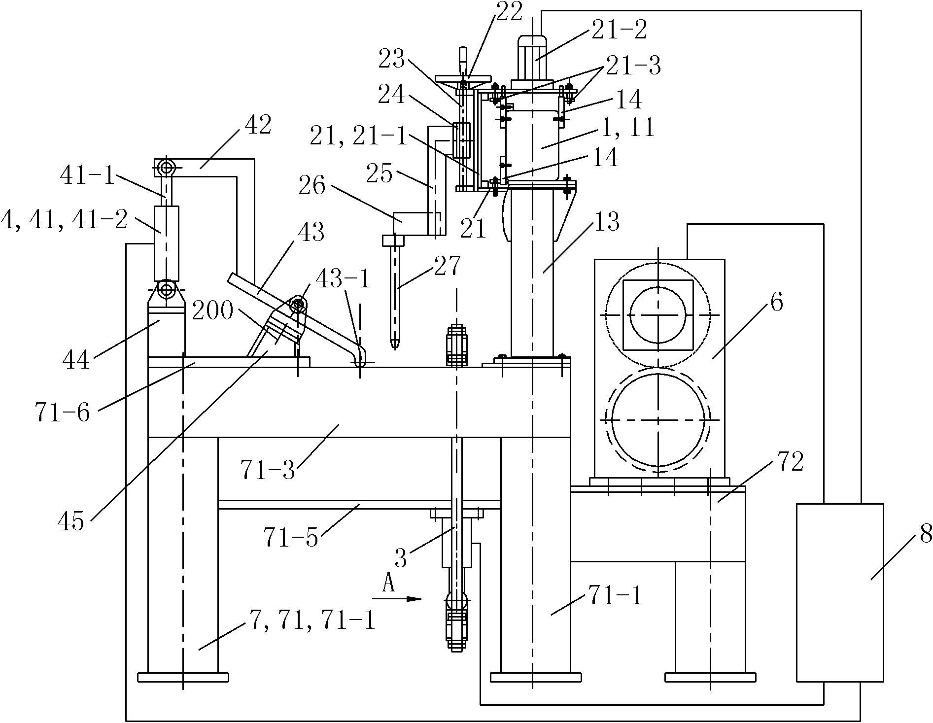
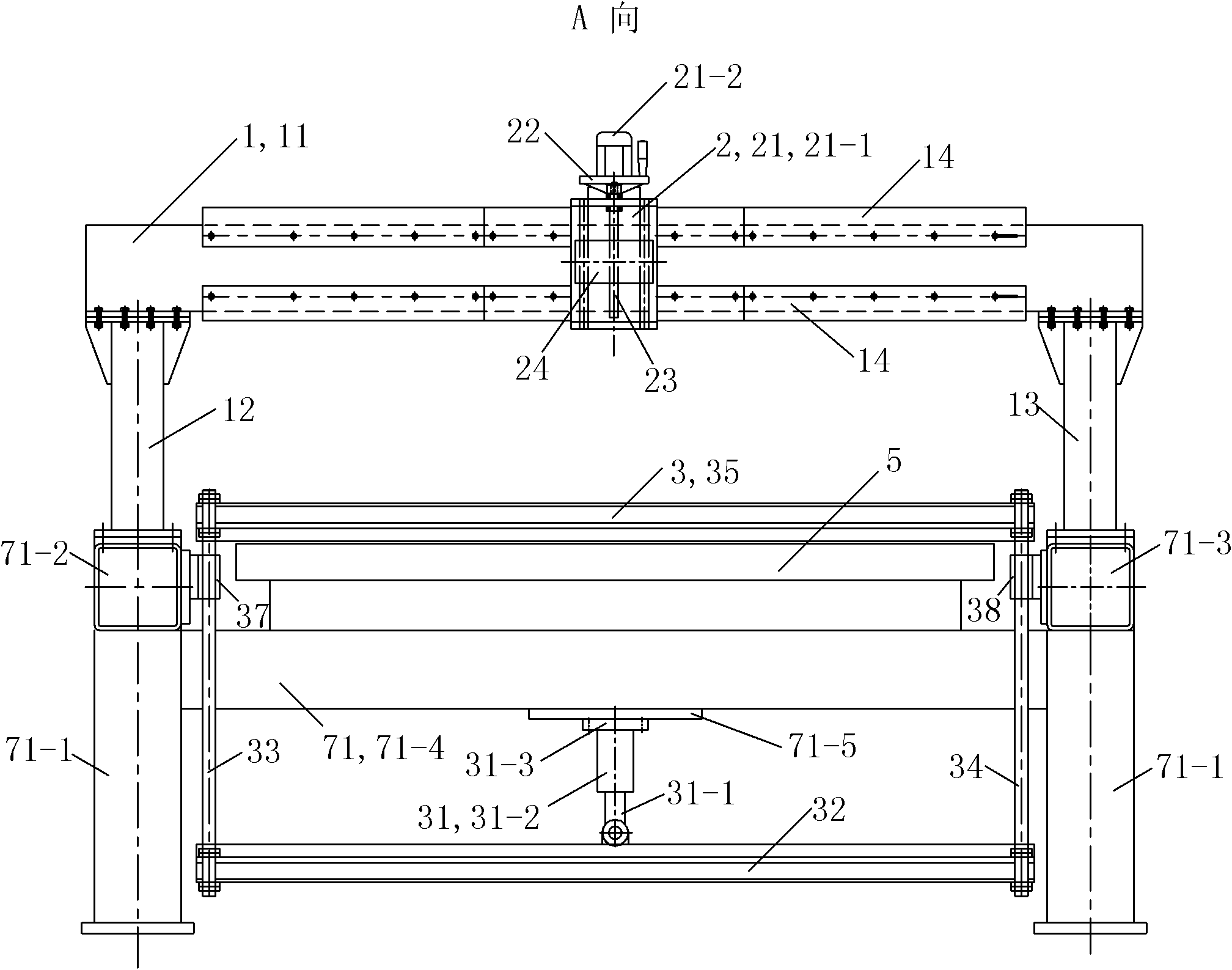
[0052] See figure 2 and image 3 , The equipment for manufacturing composite wear-resistant steel plates in this embodiment includes a gantry 1, a welding device 2, a rear side pressing device 3, a front side pressing device 4, a water cooling platform 5, a pinch roller device 6, a frame 7 and a control Box 8.

[0053] The rack 7 includes a first rack 71 and a second rack 72 located behind the first rack 71 . The first frame 71 includes a frame column 71-1, a left connecting beam 71-2, a right connecting beam 71-3, a frame crossbeam 71-4, a lower connecting beam 71-5 and a connecting plate 71-6. There are four rack columns 71-1, which are distributed on the four corners of an imaginary rectangle arranged according to the front, rear, left, and right directions. The left connecting beam 71-2 is arranged horizontally forward and backward, the front end of the left connecting be...

Embodiment 2

[0065] (Example 2, the manufacturing method of surfacing welding composite wear-resistant steel plate)

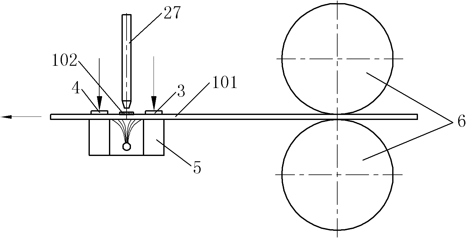
[0066] See figure 1 , the manufacturing method of the surfacing composite wear-resistant steel plate of the present embodiment has the following steps: ①The roll-shaped steel substrate 101 is spread out on the water-cooled platform 5 after the roll-shaped steel substrate 101 is rolled out, and is respectively used on the water-cooled platform 5. The front side pressing device 4 and the rear side pressing device 3 press the part of the steel substrate 101 located above the water cooling platform 5 from top to bottom along the left and right direction, and the pressure applied by the front side pressing device 4 is greater than The pressure applied by the rear side pressing device 3 makes the area between the front side pressing device 4 and the rear side pressing device 3 of the steel substrate 101 become a weldable area, and the front side pressing device 4 and the rear sid...

Embodiment 3

[0069] (Example 3, equipment and method for manufacturing surfacing composite wear-resistant steel plate)

[0070] See Figure 4 , the remaining parts of the equipment for manufacturing surfacing composite wear-resistant steel plates in this embodiment are the same as in Embodiment 1, except that the first frame 71 does not include a connecting plate 71-6. The front side pressing device is arranged on the front side of the welding torch 27 of the welding device 2 , and the structure of the front side pressing device 4 is the same as that of the rear side pressing device 3 .

[0071] When the equipment for manufacturing surfacing composite wear-resistant steel plates in this embodiment is in use, under the control of the control box 8, the piston rod of the first hydraulic cylinder of the front side pressing device 4 and the first hydraulic pressure of the rear side pressing device 3 The piston rod of the cylinder moves downward at the same time, so that the pressing plate of ...


PUM


Abstract

The invention discloses a method for manufacturing a surfacing composite wear-resistant steel plate, which comprises the following steps of: tiling a steel base plate on a water-cooled platform, and compacting the steel base plate by employing front and rear side compaction devices respectively; after a weld pass is welded, opening the front and rear side compaction devices, and conveying the steel base plate for a certain distance forward through a pinch roll device; and repeating the steps for surfacing, until a flat surfacing composite wear-resistant steel plate with a high-chromium alloy wear-resistant layer is obtained on the whole steel base plate. A piece of equipment for manufacturing the surfacing composite wear-resistant steel plate applied to the method for manufacturing the surfacing composite wear-resistant steel plate comprises a portal frame, a welding device, a rear side compaction device, a front side compaction device, a water-cooled platform, a pinch roll device and a frame, wherein the rear side compaction device is arranged on the rear side of the welding device; and the front side compaction device is arranged on the front side of a welding gun of the welding device. The composite wear-resistant steel plate welded through the manufacturing method is small in deformation and high in welding quality and is not limited to specifications.

Description

technical field [0001] The invention relates to a method for manufacturing a composite wear-resistant steel plate and equipment suitable for the method for manufacturing a composite wear-resistant steel plate. Background technique [0002] Surfacing welding refers to the welding that melts the metal by electric welding or gas welding and builds up the weldment on the surface of the weldment in order to increase or restore the size of the weldment, or to obtain special properties on the surface of the weldment. The existing composite wear-resistant steel plate manufacturing process usually adopts the method of open-arc surfacing, that is, a layer of high-chromium alloy wear-resistant layer is surfacing on the surface of ordinary Q235 steel plate, thereby greatly enhancing the wear resistance of the steel plate surface. The obtained composite wear-resistant steel plate can be used for the main friction parts between the shovel head of the scraper and the grab bucket of the loa...

Claims


Application Information

Patent Timeline
IPC IPC(8): B23K9/04B23K9/32B23K35/30B23K9/12B23K9/095
Inventor 郑少勇
Owner CHANGZHOU FUTONG WELDING
Why Eureka
Try Eureka