Dynamic controller of hinge-free aircraft

An aircraft and controller technology, applied in the aerospace field, can solve the problems of small size, air breakdown, complex and bulky mechanism at the trailing edge of the aircraft, achieve small flight weight and fuel consumption, reduce suction load, and large cavity volume. Effect

Inactive Publication Date: 2013-12-04
NORTHWESTERN POLYTECHNICAL UNIV
View PDF3 Cites 0 Cited by
  • Summary
  • Abstract
  • Description
  • Claims
  • Application Information

AI Technical Summary

Problems solved by technology

[0005] In order to overcome the problems existing in the prior art or the mechanism is complex and cumbersome; or the fuel consumption is large; or due to the limitation of the capacity of the gas tank, it cannot meet the requirements of long-term flight; It is very small, and it is easy to cause the air between the two electrodes to be broken down. The present invention proposes a hingeless aircraft dynamic controller

Method used


Image

  • Dynamic controller of hinge-free aircraft
  • Dynamic controller of hinge-free aircraft
  • Dynamic controller of hinge-free aircraft

Examples


Embodiment Construction

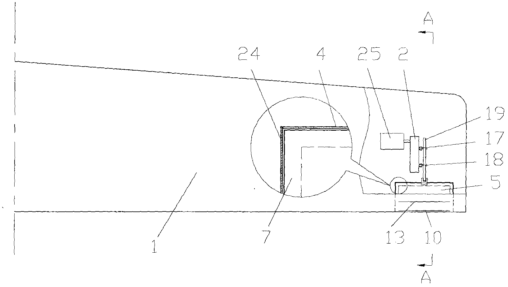
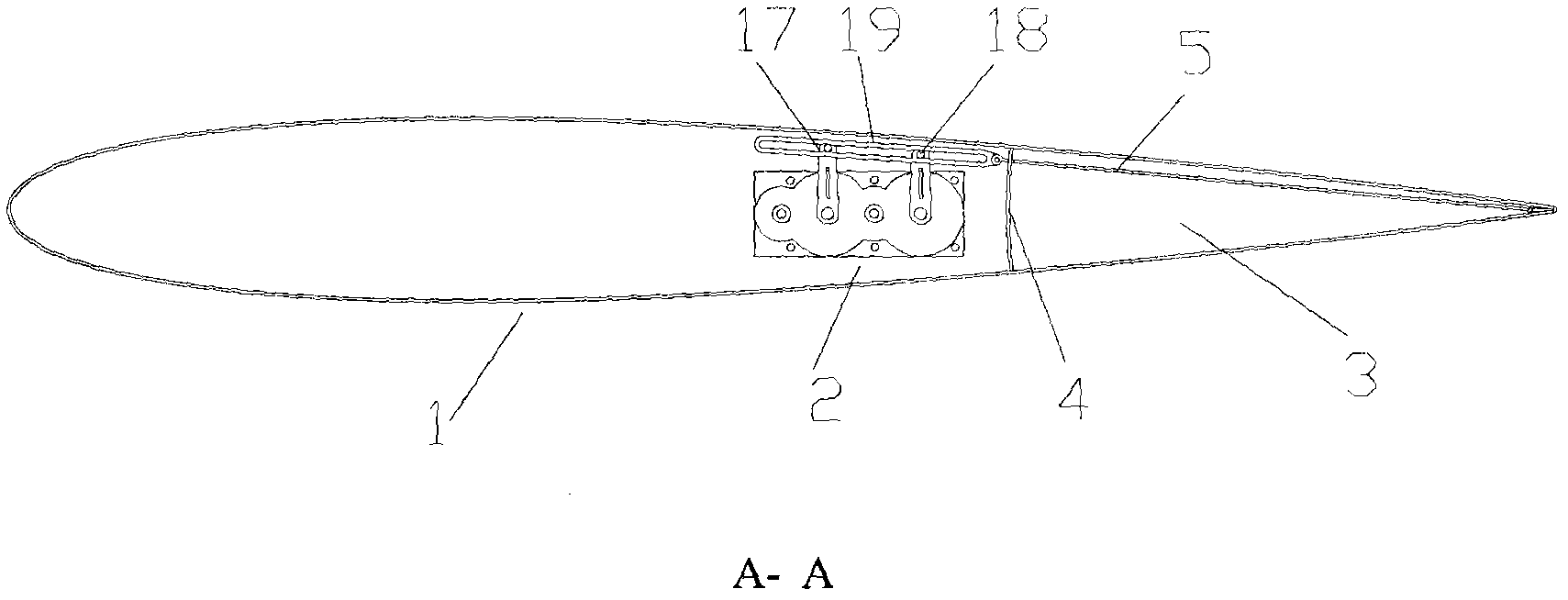
[0033] The present embodiment is two hingeless aircraft controllers, which are respectively located in the wings on both sides of the aircraft. This embodiment only describes the hingeless aircraft controller in one side of the wing.

[0034] Present embodiment takes the long straight wing of NACA0012 symmetrical airfoil as carrier.

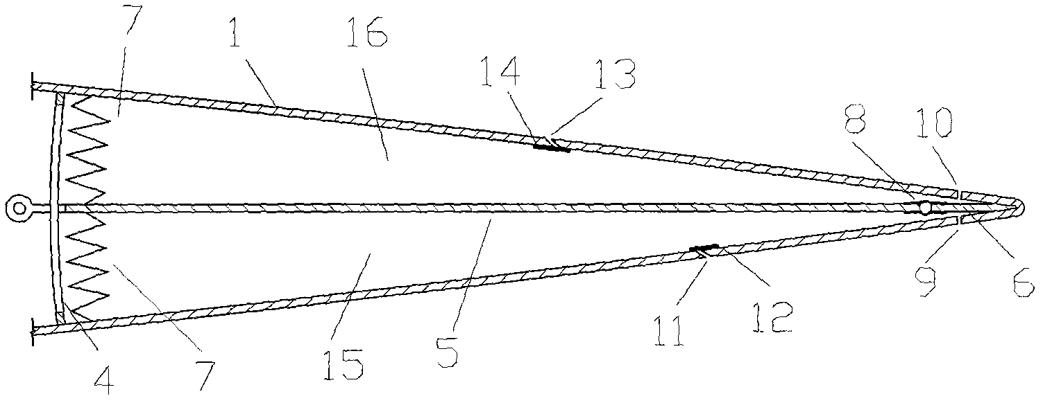
[0035] This embodiment includes a fluidic cabin body 3 , a fluidic mechanism, a transmission mechanism 2 and a motor 25 . Wherein, the jet mechanism is located at the tail edge of the wing where the jet mechanism is located in the jet cabin 3, its spanwise position is 75%-95% away from the wing root, and its chordwise position is 73%-100% of the wing chord length. The transmission mechanism 2 and the motor 25 are located in the wing and outside the jet cabin body 3 . The motor 25 drives the rotary plate 5 of the jet mechanism 3 to move up and down through the transmission mechanism 2 . Upper jet slots 10 and lower jet slots 9 are distributed a...


PUM


Abstract

The invention discloses a dynamic control mechanism of a hinge-free aircraft. A jet mechanism is positioned in a closed jet cabin in an aerofoil. A transmission mechanism and a motor are positioned in the aerofoil and out of the jet cabin; and the motor drives a rotating plate of a jet mechanism to move up and down through the transmission mechanism. An upper skin and a lower skin of the aerofoil are provided with a jet seam and an air suction seam. The jet cabin consists of an upper compartment and a lower compartment which are partitioned. The motion of the rotating plate enables the compartments to form two strokes of 'air suction' and 'air exhaust', and low-frequency high-speed airflow is generated through the air suction seam and the jet seam, so that pneumatic load distribution on the aerofoil is changed, and a pneumatic force required by dynamic control of the aircraft is generated. The dynamic control mechanism has large cavity volume and high air compression amount; high synthetic jet velocity can be generated under low driving frequency, good effect is achieved at a small angle of incidence, and flying weight and fuel oil consumption are reduced; and the dynamic control mechanism has the characteristics of simple structure and reliable start and operation, and can meet the requirement of dynamic control of the aircraft under different flying conditions.

Description

technical field [0001] The invention relates to the field of aerospace, in particular to an aircraft dynamic control device. Background technique [0002] The dynamic control of the aircraft is the control of the flight attitude of the aircraft such as pitch angle, sideslip angle and roll angle. At present, the more mature control methods are: pneumatic rudder surface control, gas rudder surface control and thrust vector control. Aerodynamic rudder surface control is to set ailerons on the wings and rely on the deflection of the aileron surface to achieve the control purpose. The advantage is that it is convenient and flexible to control, but the disadvantage is that hinges need to be set on the wings, and a hydraulic transmission device or an electric transmission device is required, so the whole mechanism is complicated and heavy. Gas rudder surface technology and thrust vectoring technology are widely used in rockets and missiles, and are also used in some fighter jets ...

Claims


Application Information

Patent Timeline
Patent Type & Authority Patents(China)
IPC IPC(8): B64C13/00B64C13/34B64C3/10B64C3/28F16H1/22
Inventor 张伟伟刘小波叶正寅宋述芳郝礼书王刚
Owner NORTHWESTERN POLYTECHNICAL UNIV
Why Eureka
Try Eureka