
Method for producing liquefied natural gas by using coke oven gas

A technology of liquefied natural gas and coke oven gas, which is applied in the direction of gas fuel, petroleum industry, fuel, etc., and can solve problems such as risks that cannot cope with market changes

Active Publication Date: 2011-07-06
BEIJING ZHONGKE RUIAO ENERGY TECH CO LTD
View PDF2 Cites 35 Cited by
  • Summary
  • Abstract
  • Description
  • Claims
  • Application Information

AI Technical Summary

Problems solved by technology

Therefore, a single methanol production process plan obviously cannot cope with the risk of market changes

Method used


Image

  • Method for producing liquefied natural gas by using coke oven gas
  • Method for producing liquefied natural gas by using coke oven gas
  • Method for producing liquefied natural gas by using coke oven gas

Examples


Embodiment 1

[0036] This example is used to illustrate the method for producing liquefied natural gas from coke oven gas provided by the present invention.

[0037] The main composition (volume percentage) of raw coke oven gas is: 58%H 2 , 21%CH 4 , 9% CO, 5% N 2 , 4% CO 2 , 3%C m h n Wait.

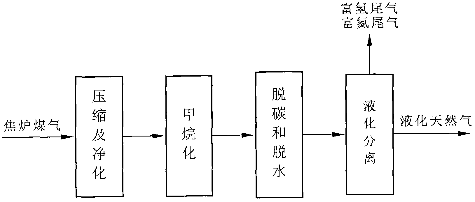
[0038] Such as figure 1 As shown, the raw coke oven gas is purified and compressed in the early stage to remove tar, benzene, naphthalene, sulfur and other impurities; then the methanation reaction is carried out to remove the CO and CO in the raw gas 2 with H 2 The reaction produces CH 4 , so as to increase the methane concentration of the feed gas, and then deCO2 the feed gas 2 and dehydration.

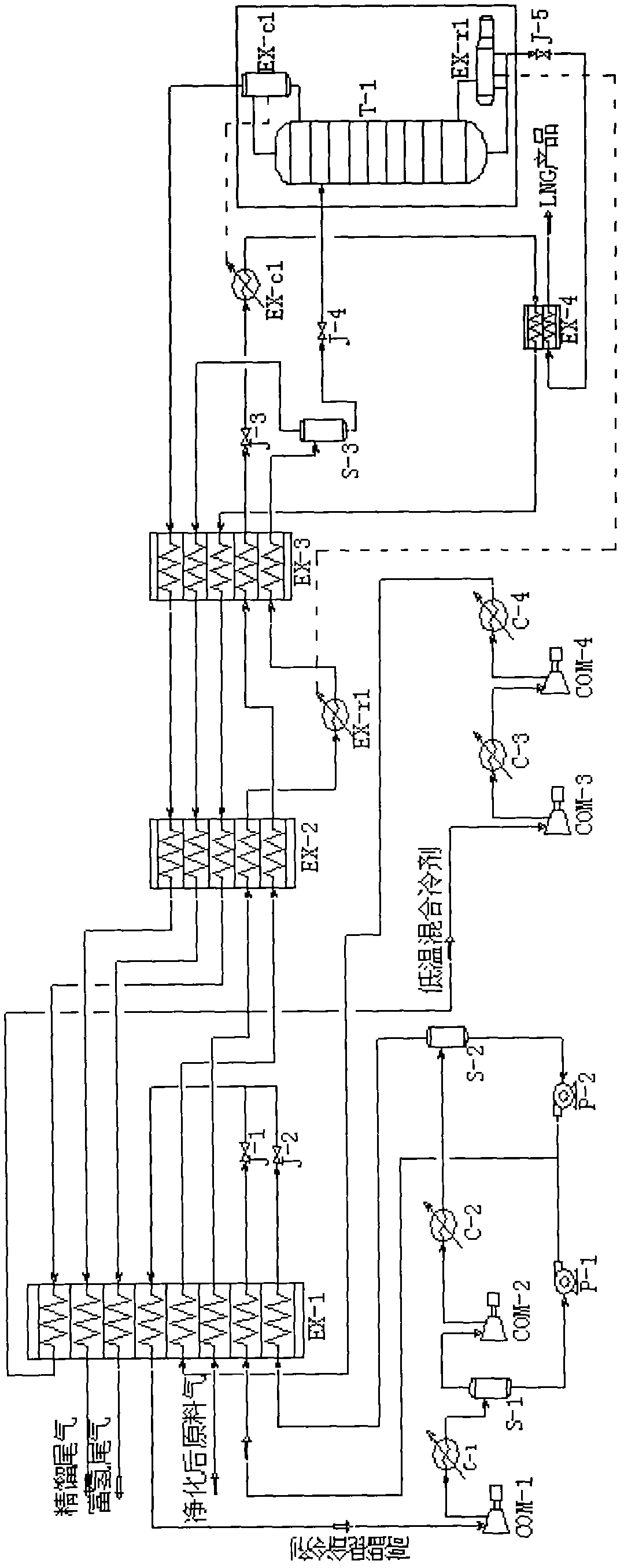
[0039] The specific operation method is: the coke oven gas is pressurized to 0.4MPa by the screw compressor and then enters the pretreatment process. The pretreatment adopts the temperature-swing-pressure-swing adsorption method to remove benzene, naphthalene, tar and HCN, using the hydrogen-rich...

Embodiment 2

[0049] This example is used to illustrate the method for producing liquefied natural gas from coke oven gas provided by the present invention.

[0050] According to the same method as Example 1, the difference is:

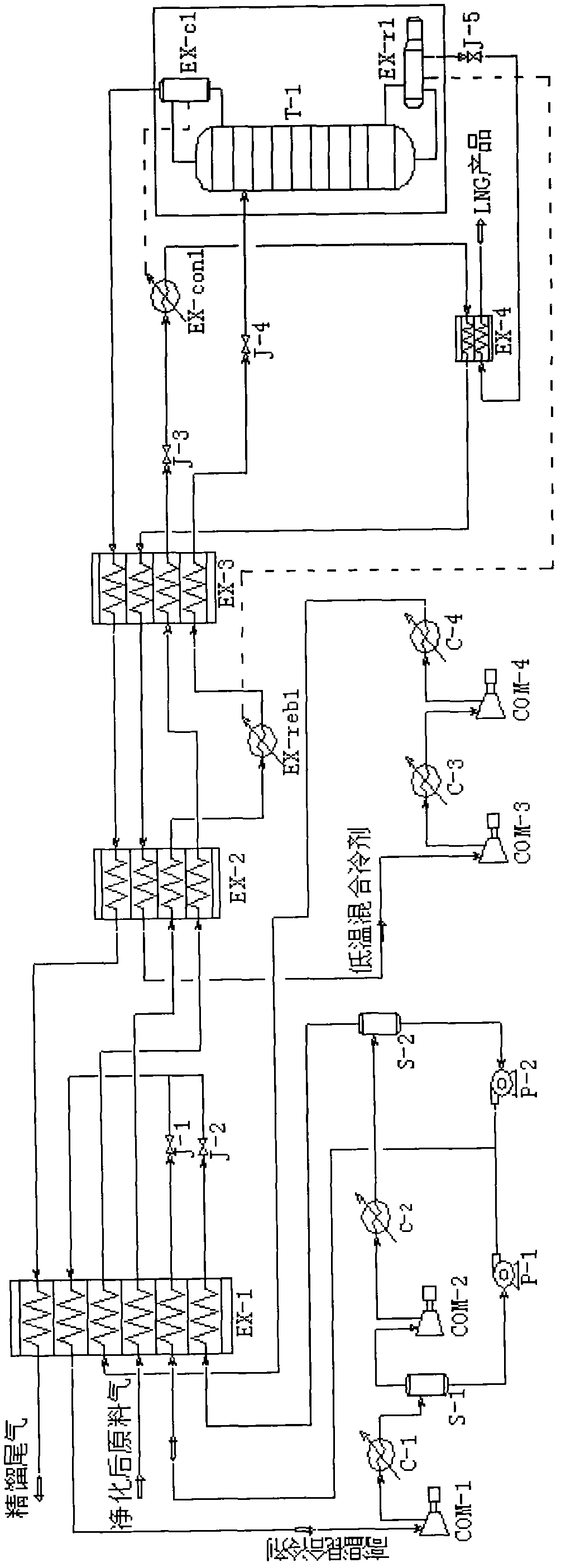
[0051] After the mixed refrigerant in the low temperature zone comes out from the hot end of the second heat exchanger EX-2, it does not enter the cold end of EX-1 as in Example 2, but directly returns to the first section of the compressor inlet COM-3 for compression (due to the -2 The mixed refrigerant coming out of the hot end is a low-temperature fluid with a temperature of -40 to -60°C, so the low-temperature mixed refrigerant compressor of this embodiment adopts a low-temperature compressor; while the low-temperature mixed refrigerant compressor of embodiment 1 adopts a Normal temperature compressor can be);

[0052] After the purified raw gas comes out from the cold end of the third heat exchanger EX-3, it directly enters the cryogenic rectification tower T...


PUM


Abstract

The invention provides a method for producing liquefied natural gas by using coke oven gas. The method comprises the following steps: (1) the coke oven gas is pretreated to remove benzene, naphthalene, tar and HCN (hydrogen cyanide); (2) sulfur is removed; (3) carbon is removed and the coke oven gas is dried; (4) the coke oven gas is led to a first heat exchanger and pre-cooled; (5) the pre-cooled coke oven gas passes through a second heat exchanger, a reboiler at the bottom of a low-temperature rectifying tower and a third heat exchanger in sequence, so that the temperature is lowered step by step; (6) gaseous liquid coming out of the third heat exchanger is led to a gas-liquid separator for gas-liquid separation, then the liquid coming out of the gas-liquid separator enters the low-temperature rectifying tower, and a liquefied natural gas product is acquired at the bottom of the low-temperature rectifying tower; and otherwise, the gaseous liquid coming out of the third heat exchanger is directly led to the low-temperature rectifying tower, and the liquefied natural gas product is acquired at the bottom of the low-temperature rectifying tower. The method for producing the liquefied natural gas by using the coke oven gas as raw material has the advantages of high output as well as low energy consumption and cost, and is easy to operate.

Description

technical field [0001] The invention relates to a method for producing liquefied natural gas from coke oven gas. Background technique [0002] my country is the world's largest producer, consumer and exporter of coke. In 2004, the coke output was 224 million tons, accounting for 56% of the global output. At the same time, more than 70 billion cubic meters of coke oven gas was produced. Half of the coke oven gas is used to return to the furnace to support combustion, and the other half needs to be recovered by a special device. Because my country's coking industry only focuses on coke production and ignores the recovery of chemical products, coke oven gas, the main by-product of coking production, is directly burned and released in large quantities, commonly known as "lighting sky lanterns". The resulting economic losses amounted to tens of billions of dollars, resulting in a great waste of scarce resources, and also caused great pollution to the environment. According to e...

Claims


Application Information

Patent Timeline
IPC IPC(8): C10L3/10C10L3/08
Inventor 任小坤史红兵孙郁张武
Owner BEIJING ZHONGKE RUIAO ENERGY TECH CO LTD
Learn More