Capacitor bootstrap drive circuit and method of switched reluctance motor

A switched reluctance motor and drive circuit technology, which is applied in the direction of AC motor control, electrical components, electronic commutators, etc., can solve the problems of high circuit cost, large reference voltage, and failure to work normally and continuously, achieving strong practicability, The effect of simple circuit structure

Inactive Publication Date: 2011-07-20
SOUTHEAST UNIV
View PDF4 Cites 14 Cited by
  • Summary
  • Abstract
  • Description
  • Claims
  • Application Information

AI Technical Summary

Problems solved by technology

The disadvantage of this circuit is that the structure of the multi-power supply circuit is complex and the circuit cost is high.
The principle of the single power supply drive circuit formed by the bootstrap diode is to design the relative delay circuit of the bootstrap diode and the upper and lower tubes, and use the principle of reverse cut-off of the diode, combined with the delay signal to realize the first opening of the lower switch tube, Then turn on the control sequence of the upper switching tube to avoid the high voltage generated in the motor coil when the upper and lower switching tubes are turned on at the same time, causing the refer

Method used


Image

  • Capacitor bootstrap drive circuit and method of switched reluctance motor
  • Capacitor bootstrap drive circuit and method of switched reluctance motor
  • Capacitor bootstrap drive circuit and method of switched reluctance motor

Examples


Embodiment Construction

[0023] Below in conjunction with accompanying drawing and specific embodiment, further illustrate the present invention, should be understood that these embodiments are only for illustrating the present invention and are not intended to limit the scope of the present invention, after having read the present invention, those skilled in the art will understand various aspects of the present invention Modifications in equivalent forms all fall within the scope defined by the appended claims of this application.

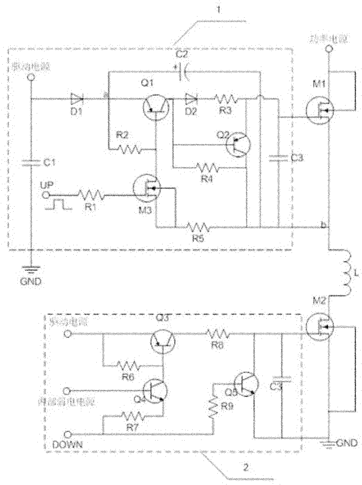
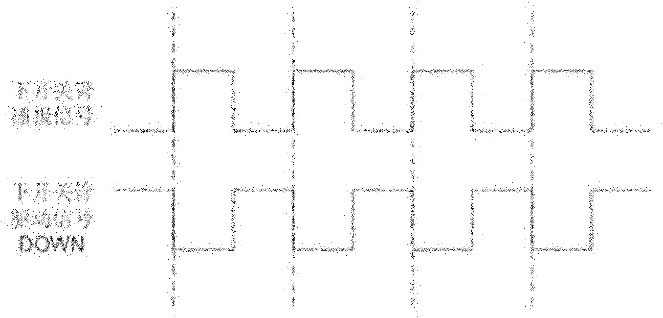
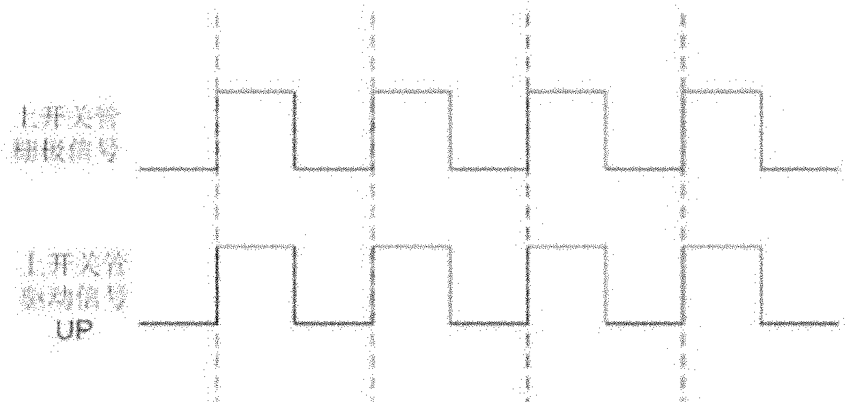
[0024] Such as figure 1 As shown, the upper switching tube driving circuit 1 receives the upper switching tube driving signal UP, and the lower switching tube driving circuit 2 receives the lower switching tube driving signal DOWN, respectively controlling the upper and lower switching tubes of the switched reluctance motor. The drive signal UP of the upper switch tube is connected to the first resistor R1, and the other end of the resistor is connected to the gate of th...


PUM


Abstract

The invention discloses a capacitor bootstrap drive circuit of a switched reluctance motor, consisting of an upper switching tube drive circuit and a lower switching tube drive circuit. The upper switching tube drive circuit consists of a first charging circuit, a first discharging circuit and a bootstrap capacitance circuit, and the lower switching tube drive circuit consists of a second charging circuit and a second discharging circuit. The invention also discloses a drive method using the drive circuit. By charging a bootstrap capacitor to the drive power supply voltage only when a lower switching tube is turned on and turning on an upper switching tube with the voltage of the bootstrap capacitor, the method avoids the problem that the motor works abnormally since the upper switching tube has a deficient grid voltage due to the voltage raising of a terminal b and is failed to be turned on when a phase winding of the motor is turned on. With the bootstrap drive circuit constituted by a bootstrap capacitor, a diode, a commonly-used resistor, a triode and other elements, the switching tubes can be driven in real time with driving signals. The invention has advantages of simple circuit structure and strong practicability.

Description

technical field [0001] The invention relates to a switched reluctance motor, in particular to a driving circuit and a driving method of the switched reluctance motor. Background technique [0002] Switched reluctance motors have some unique advantages, such as simple structure, firmness, maintenance-free, large torque and low current at start-up and low speed; wide range of high-speed constant power range, good performance, and excellent performance in a wide range of speed and power. High output and high efficiency; it can operate with phase loss and has strong fault tolerance; it can be flexibly controlled and can easily realize four-quadrant operation; it has strong regenerative braking ability, etc. This makes the switched reluctance motor system widely used in household appliances, general industry, servo and speed control systems, traction motors, high-speed motors, aerospace and other fields. A switched reluctance motor is an electromechanical energy conversion devic...

Claims


Application Information

Patent Timeline
IPC IPC(8): H02P6/14H02P25/08H02M3/07
Inventor 钟锐徐宇柘项国富孙伟锋陆生礼时龙兴
Owner SOUTHEAST UNIV
Why Eureka
Try Eureka