
Multifunctional self-excited oscillation abrasive water jet generating device

A technology of abrasive water jet and self-excited oscillation, which is applied in the direction of spraying devices, spraying devices, liquid spraying devices, etc., can solve the problems of low reuse rate, high production cost, and shortened service life, so as to reduce workload and structure Simple, cost-saving effect

Active Publication Date: 2011-07-27
CHONGQING UNIV
View PDF14 Cites 35 Cited by
  • Summary
  • Abstract
  • Description
  • Claims
  • Application Information

AI Technical Summary

Problems solved by technology

[0003] (1) Due to the integral molding, there are processing difficulties, low precision of the resonator body, low yield, high production cost, and low reuse rate, and it will be directly scrapped once damaged;
[0004] (2) Self-excited oscillating abrasive water jets are mostly used for rock breaking and cutting in engineering. Most of the above published patents only involve pure water jets. Once abrasive jets are used, the upstream and downstream nozzles are easy to wear and deform, and the outlet jet erosion cutting efficiency is greatly reduced. shortened service life;
[0005] (3) Self-excited oscillating nozzles with limited installation positions cannot be redesigned
[0006] Therefore, the wider application of self-excited oscillating abrasive water jet nozzles in engineering is limited, and it is not conducive to the laboratory test research of self-excited oscillating abrasive water jet nozzles

Method used


Image

  • Multifunctional self-excited oscillation abrasive water jet generating device
  • Multifunctional self-excited oscillation abrasive water jet generating device
  • Multifunctional self-excited oscillation abrasive water jet generating device

Examples


Embodiment Construction

[0021] The present invention will be further described below in conjunction with the accompanying drawings.

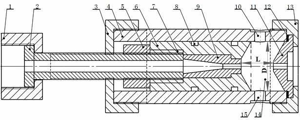
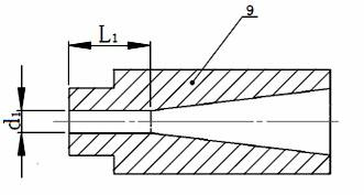
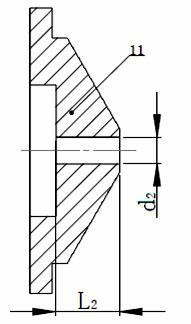
[0022] see figure 1 The shown multifunctional self-excited oscillating abrasive water jet generator includes a first end cover 3 and a second end cover 13 which are respectively threaded on the left end and the right end of the resonance cylinder 4;

[0023] The inner wall cavity of an upstream nozzle sleeve 6 is in the shape of a stepped hole, a metal threaded sleeve 7 is provided on the left part of the inner wall cavity, and two ring grooves are arranged on the outer wall, and "O"-shaped sealing rings 8 are respectively arranged in the two ring grooves, The outer wall of the upstream nozzle sleeve 6 cooperates with the inner wall of the resonance cylinder 4;

[0024] An adjusting screw barrel 2 passes through the connecting nut 1 and is threadedly connected with the central hole of the first end cap 3, the locking nut 5 and the metal threaded sleeve 7 arranged on t...


PUM


Abstract

The invention discloses a multifunctional self-excited oscillation abrasive water jet generating device, which comprises an upstream nozzle, a downstream nozzle, an adjusting screw, a resonance cylinder, a first end cover and a second end cover. The device is characterized in that: the left part of the inner wall cavity of an upstream nozzle bush is provided with a metal threaded bush, and the outer wall of the upstream nozzle is matched with the inner wall of the resonance cylinder; the adjusting screw passes through a connecting screw cap and is sequentially in fit connection with the central hole of the first end cover, a locking screw cap and the metal threaded bush; the upstream nozzle is arranged on the right middle part of the inner wall cavity of the upstream nozzle bush, and the downstream nozzle is arranged between the right end of the resonance cylinder and the second end cover; the right end of the upstream nozzle, the left end of the downstream nozzle and the inner wall of the resonance cylinder positioned between the upstream nozzle and the downstream nozzle form a resonance chamber; and an air inlet formed on the resonance cylinder and an adjusting screw mounting hole are communicated with the resonance chamber. The device has simple structure, and is convenient for operation; the device has multiple testing functions; and compared with other jet generating devices, not only the experiment time can be greatly shortened, but also the experiment expenditure can be saved.

Description

technical field [0001] The invention relates to a water jet testing device, in particular to a multifunctional self-excited oscillating abrasive water jet generating device, which is suitable for coal seam slit cutting head, PCD (Polycrystalline diamond) drill bit, roller cone bit matching and stone material cutting, Structural parameter optimization of self-excited oscillating abrasive water jet nozzle for flushing etc. Background technique [0002] Self-excited oscillating pulsed abrasive water jet is a new type of high-efficiency abrasive water jet developed by using the principles of multiphase fluid dynamics, turbulent flow mechanics, fluid boundary layer theory, fluid resonance and liquid elasticity. It has been widely used in Coal mining, oil drilling, rock cutting and cleaning and other fields. It does not require an excitation source, no sealing of moving parts, but relies on the material of the nozzle and its own structural characteristics (wear-resistant material...

Claims


Application Information

Patent Timeline
IPC IPC(8): B05B17/04B05B1/02B05B1/00B05B15/00
Inventor 卢义玉葛兆龙汤积仁左伟芹刘勇章文峰
Owner CHONGQING UNIV
Learn More