Multi-gear pump stepped variable system

A technology of variable displacement system and gear pump, which is applied in the direction of pump, pump control, rotary piston type/oscillating piston type pump combination, etc. It can solve the situation where high power is not suitable, the structure of variable displacement plunger pump is complex, and oil pollution resistance Low capacity and other problems, to achieve the effect of strong oil pollution resistance, simple structure and high reliability

Inactive Publication Date: 2011-08-03
JILIN UNIV
View PDF5 Cites 6 Cited by
  • Summary
  • Abstract
  • Description
  • Claims
  • Application Information

AI Technical Summary

Problems solved by technology

The most common methods are: 1. Use the flow control valve to adjust. The main problem of this method is that the power loss is large, so it is not suitable for high-power applications; 2. Use the variable pump system. Directional piston pump, this flow adjustment method has high efficiency and is

Method used


Image

  • Multi-gear pump stepped variable system
  • Multi-gear pump stepped variable system
  • Multi-gear pump stepped variable system

Examples


Embodiment Construction

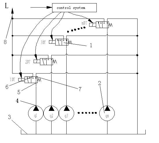
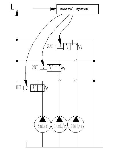
[0015] The present invention includes at least three gear pumps 1 (q1, q2, q3...qn) with different displacements, at least three electromagnetic reversing valves 2 (1DT, 2DT, 3DT...nDT), each gear pump 1 has A separate oil discharge port 4, the oil discharge port 4 of each gear pump 1 is connected to the oil inlet 5 of the electromagnetic reversing valve 2, and the other two oil ports 6 and 7 of the electromagnetic reversing valve 2 are respectively connected to the oil tank 3 and the main drain Oil port 8 communicates. The total oil discharge port 8 communicates with the system L, that is, the oil discharge is sent into the system through the total oil discharge port.

[0016] All the gear pumps of the present invention are coaxially connected and driven by a prime mover. Prime mover refers to power input equipment such as motors and engines.

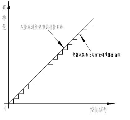
[0017] The displacement of the pumps of the present invention is arranged in a proportional number sequence, how many gear pumps th...


PUM


Abstract

The invention relates to a multi-gear pump stepped variable system which belongs to the field of pumps. The invention aims at providing a multi-gear pump stepped variable system for realizing stepped regulation of displacement by utilizing the combination of a plurality of gear pumps with different displacements. The multi-gear pump stepped variable system comprises at least three gear pumps with different displacements and at least three electromagnetic reversing valves, wherein each gear pump is provided with an independent oil discharge outlet, the oil discharge outlet of each gear pump is connected with an oil inlet of the electromagnetic reversing valves, and the other two oil ports of the electromagnetic reversing valves are respectively communicated with an oil tank and a main oil discharge port. The on-off of the electromagnetic reversing valves can be controlled by a single-chip machine, a PLC (Programmable Logic Controller) or a computer and the like so that each gear pump is controlled to supply oil to the system or not, thereby realizing that the flow of the system is controlled by utilizing a smaller displacement variation gradient.

Description

technical field [0001] The invention belongs to the field of pumps. Background technique [0002] Hydraulic transmission is a technical science that converts, transmits, distributes and controls energy with liquid as the working medium. It uses the hydraulic pump to convert the mechanical energy of the prime mover into the pressure energy of the liquid, and converts the pressure energy of the liquid into mechanical energy by means of hydraulic actuators (cylinders or motors), thereby driving the working mechanism to achieve linear reciprocating motion and rotary motion. The working mechanism often has various requirements for force and speed, so it needs to be transmitted and distributed through various control valves and pipelines. Hydraulic transmission is widely used in machine tools, automobiles, airplanes, ships, engineering machinery, plastic machinery, testing machinery, metallurgical machinery and mining machinery and other fields due to its incomparable advantages ...

Claims


Application Information

Patent Timeline
IPC IPC(8): F04C11/00F04C14/02
Inventor 刘昕晖王同建
Owner JILIN UNIV
Why Eureka
Try Eureka