
Method for manufacturing optical fiber preform

A manufacturing method and preform technology, which are applied in manufacturing tools, glass manufacturing equipment, optics, etc., can solve the problems of fracture of the base material, different thermal conductivity and specific heat, and the inability to fully obtain the effect of suppressing diameter variation.

Active Publication Date: 2011-08-03
SHIN ETSU CHEM CO LTD
View PDF3 Cites 1 Cited by
  • Summary
  • Abstract
  • Description
  • Claims
  • Application Information

AI Technical Summary

Problems solved by technology

[0009] In this case, there is a problem that in order to draw the base material silicon ingot with a large diameter and a variation in the outer diameter in the longitudinal direction, it is necessary to increase the size of the drawing furnace too much in accordance with the variation in the outer diameter. The airtight mechanism of the base material silicon ingot inserted into the furnace becomes complicated
The reason is that at the end of drawing, the thermal conductivity and specific heat are different between the vitrified part and the unsintered part, so even at the same temperature, the drawn part changes greatly
Moreover, if the conveying amount of the base material is too large, there will also be a problem that the base material breaks at the junction of vitrification.
[0016] As a method of preventing the upper part of the drawing end side from being drawn first, as described in Patent Document 2, a method of covering the upper part of the base material silicon ingot with a heat-resistant heat-insulating jig and performing drawing is described. However, in It takes man-hours to install jigs before drawing, and especially for base material silicon ingots with a diameter of φ150 mm or more, the effect of suppressing diameter fluctuations cannot be sufficiently obtained

Method used


Image

  • Method for manufacturing optical fiber preform
  • Method for manufacturing optical fiber preform
  • Method for manufacturing optical fiber preform

Examples


Embodiment 1

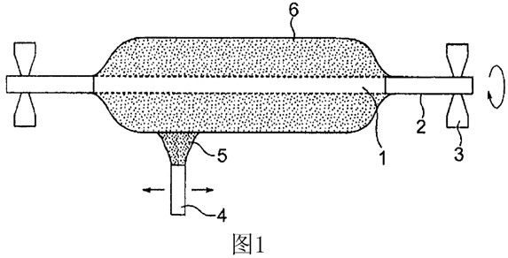
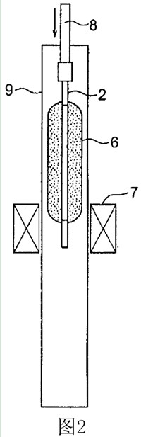
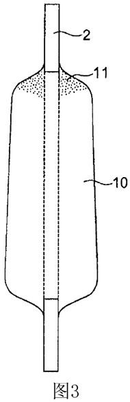
[0062] On a target made of synthetic quartz glass including a mandrel, glass particles are deposited by external vapor deposition to produce a porous glass base material. Hold the dummy rod installed at one end of the porous glass base material, insert the porous glass base material into the sintering furnace in a vertically suspended state, heat at 1500°C, and make He, Cl 2 , O 2 Wait for the process gas to flow, and at the same time make the porous glass base material move downward to make it transparent and vitrified from one direction. At the end of this step, sintering is completed with an unsintered portion remaining on the upper portion, and a base material silicon ingot is obtained.

[0063] The outer diameter of the base material silicon ingot obtained was measured along the longitudinal direction, and the results are shown in Figure 6 middle. The left end of the horizontal axis in the figure indicates the sintering start side, and the right end side indicates the...


PUM


Abstract

Disclosed is a method for manufacturing an optical fiber preform that, specifically, is able to suppress outer diameter fluctuations in the preform in the area where the drawing of a preform ingot ends and to yield a preform of uniform diameter in the length direction. A preform manufacturing method, which consists of a step in which a porous glass preform (6) is manufactured by producing silica powder from a compound containing silicon, a step in which a preform ingot (10) is obtained by sintering and vitrifying the porous glass preform (6) at high temperatures, and a step in which the preform ingot (10) is drawn and the diameter thereof is reduced by exerting tension on a heated portion while sequentially moving a heating means in a relative manner along the length of the preform ingot (10), is characterized by leaving an unsintered portion (11), which has not been completely vitrified, at one end of the sintered preform ingot (10), and by beginning the drawing from the unsintered portion (11) side in the drawing and diameter-reducing step.

Description

technical field [0001] The present invention relates to a method for manufacturing a preform for an optical fiber, capable of suppressing the outer diameter of the preform especially at the end of drawing when heating and drawing a silicon ingot as a base material made of synthetic quartz to manufacture a preform for an optical fiber change. In addition, this application is related to the following Japanese application. With respect to the designated countries whose approved documents are incorporated by reference, the contents described in the following applications are incorporated by reference into this application as part of this application. [0002] Japanese Patent Application No. 2008-228909 was filed on September 5, 2008. Background technique [0003] For preforms for optical fibers, there are known vapor phase axial deposition methods and external vapor phase deposition methods, in which silicon compounds such as silicon tetrachloride are hydrolyzed in an oxygen-h...

Claims


Application Information

Patent Timeline
Patent Type & Authority Applications(China)
IPC IPC(8): C03B37/012C03B37/027G02B6/00
CPCC03B37/01446C03B37/0124C03B37/01466Y02P40/57
Inventor 清水佳昌
Owner SHIN ETSU CHEM CO LTD
Features
  • Generate Ideas
  • Intellectual Property
  • Life Sciences
  • Materials
  • Tech Scout
  • Unparalleled Data Quality
  • Higher Quality Content
  • 60% Fewer Hallucinations
Learn More