
Air-conditioning system of closed artificial light plant factory

An air-conditioning system and artificial light technology, applied in air-conditioning systems, botany equipment and methods, heating and ventilation control systems, etc., can solve the problem of unbalanced air-conditioning running time, large capacity of air-conditioning systems, and large difference in cooling load between day and night, etc. problem, to achieve the effect of reducing installed capacity, low ambient temperature at night, and increasing cooling load at night

Active Publication Date: 2011-08-10
CHINA YANGZI GRP CHUZHOU YANGZI AIR CONDITIONERCO
View PDF7 Cites 8 Cited by
  • Summary
  • Abstract
  • Description
  • Claims
  • Application Information

AI Technical Summary

Problems solved by technology

Due to technical limitations, the existing artificial light sources that can be used on a large scale have the problem of large heat dissipation
This heat is the main cooling load of the plant factory in summer. For example, turning on the artificial light source during the day, coupled with the heat introduced through the enclosure structure and the heat generated by the plant growth, in order to maintain the appropriate temperature for plant growth, the air conditioning system during the day The cooling load is much greater than the cooling load at night, which has the following disadvantages: 1. The air conditioning system has a large capacity, which increases the initial investment of equipment; 2. The cooling load difference between day and night is large, the running time of the air conditioner is uneven, and the utilization rate of the equipment is not high; 3. 1. The ambient temperature is high during the day, at this time the energy efficiency ratio of the air conditioner host decreases, and the system does not save energy

Method used


Image

  • Air-conditioning system of closed artificial light plant factory
  • Air-conditioning system of closed artificial light plant factory

Examples


Embodiment

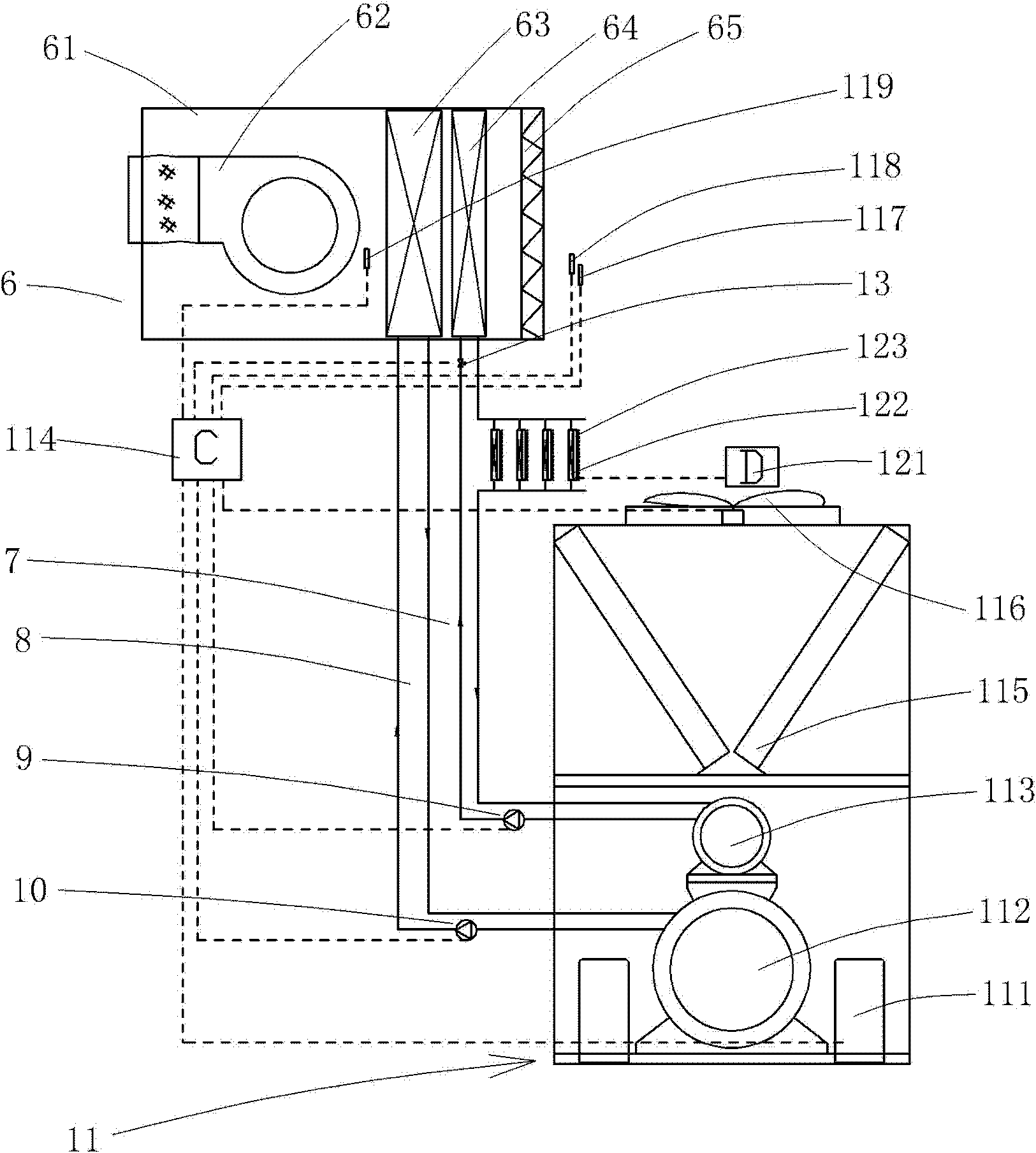
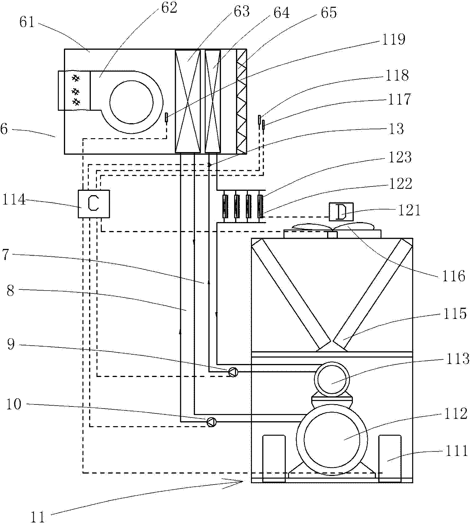
[0025] Example: see figure 1 , the air-conditioning system of the closed artificial light plant factory of the present embodiment,

[0026] Including air handling unit 6, artificial light source, 123 artificial light source heat recovery device 122, timing controller 121, heat recovery type air conditioning unit 11;

[0027] The air handling unit casing 61, fan 62 and air filter 65 form a public air duct. The surface cooler 63 and the heating coil 64 are connected in series in the common air duct, and the air flow first flows through the heating coil 64 and then flows through the surface cooler 63 . The heat recovery heat exchanger 113 utilizes the heat of condensation discharged from the compressor 111 during the cooling of the heat recovery type air-cooled heat pump chiller and hot water unit or the heat dissipation of the artificial light source heat dissipation recovery device 122 to produce hot water, and passes through the hot water circulation pump 9 and the hot water ...


PUM


Abstract

The invention discloses an air-conditioning system of a closed artificial light plant factory. The air-conditioning system comprises an artificial light source, an artificial light source heat reclaiming device, a timing controller and a heat reclamation air-conditioning unit; the timing controller controls on and off of the artificial light source, the artificial light source is turned off at daytime to form a dark period of plant growth, and the artificial light source is turned on at night to form a light period of plant growth; the artificial light source heat reclaiming device absorbs the heat of the artificial light source, then the heat is absorbed by the heat reclamation air-conditioning unit, and the heat is supplied to the plant factory through an air treatment unit; and the heat reclamation air-conditioning unit and the air treatment unit are controlled by the controller. The timing controller controls the artificial light source to be turned on and off alternately at daytime and night, so that cold load at daytime is reduced, cold load at nigh is increased, the utilization rate of the air-conditioning unit is improved, the installed capacity is reduced and the initial investment is reduced.

Description

Technical field: [0001] The invention relates to an air-conditioning system of a closed artificial light plant factory. Background technique: [0002] "Plant factory" refers to a year-round plant cultivation system through artificial environment control and computerized production management. Plants are planted in a closed space like a factory building, and the temperature, humidity, carbon dioxide, oxygen, fertilizer, nutrients, and light required for their growth are all controlled, and they are no longer affected by the external climate environment. Homogenization and high yield characteristics. [0003] According to the population report released by the United Nations, the global population will reach 9.3 billion by 2050. If we rely on the traditional farming method of relying on the sky, all the arable land in the world is currently operating at almost full capacity to barely support the current more than 600 million people. million people. So a fundamental solution ...

Claims


Application Information

Patent Timeline
Patent Type & Authority Applications(China)
IPC IPC(8): F24F1/00F24F13/30F24F11/00A01G9/24
CPCY02A40/25Y02P60/14
Inventor 陈凌云曾晓程杨其长魏灵玲沈增友
Owner CHINA YANGZI GRP CHUZHOU YANGZI AIR CONDITIONERCO
Learn More