Large-scale numerical control gear machining machine tool

A technology for processing machine tools and gears, which is applied in the field of CNC machine tools, can solve the problems of low-speed and stable tooth surface interpolation accuracy of the table, the processing problems of large-scale cylindrical gears, and the inability to simulate gear cutting with grinding wheels, etc., so as to improve processing accuracy and processing efficiency, reduce Effects of Interference, Guaranteed Accuracy and Rigidity

Active Publication Date: 2011-08-17
秦川机床工具集团股份公司
View PDF7 Cites 51 Cited by
  • Summary
  • Abstract
  • Description
  • Claims
  • Application Information

AI Technical Summary

Problems solved by technology

For bevel gears made by Klingelnberg, the blade track of the cutter head is not a surface of revolution, so it cannot be made into a grinding wheel to simulate tooth cutting, so it cannot be ground like Gleason. High-precision hard-toothed gears can only use hard scraping technology; when the diameter of the bevel gear increases , there are not only problems in the processing of large cylindrical gears, the stability of the table at low speed, and the interpolation accuracy of the tooth surface, but also the increase in the diameter of the cutter head, which brings many problems to machine tool manufacturing.

Method used


Image

  • Large-scale numerical control gear machining machine tool
  • Large-scale numerical control gear machining machine tool
  • Large-scale numerical control gear machining machine tool

Examples


Embodiment Construction

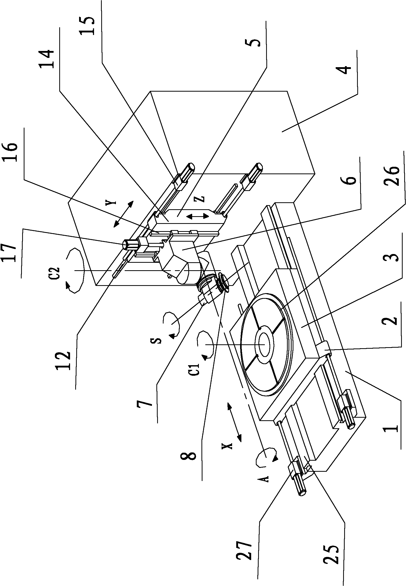
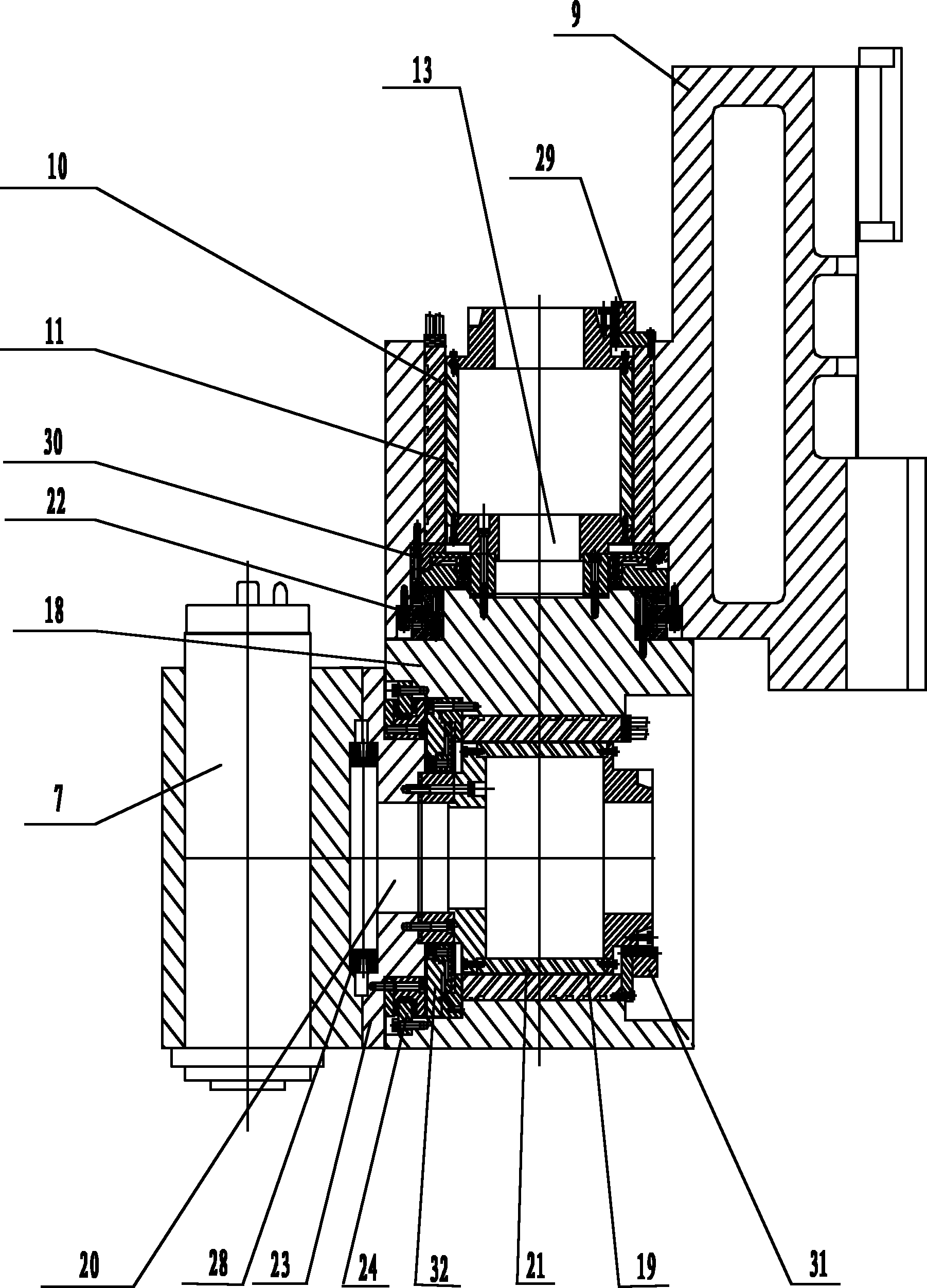
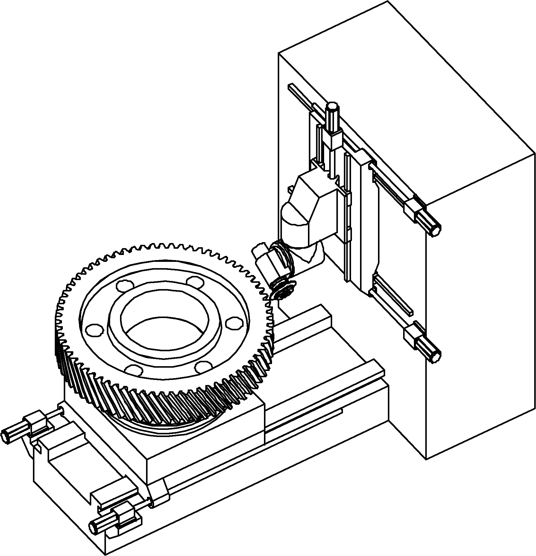
[0024] Attached below figure 1 , 2 , 3, 4, 5 describe an embodiment of the present invention.

[0025] A large CNC gear processing machine tool with a horizontal base 1 and a vertical support 4. The vertical support 4 is arranged at the end of the horizontal base 1 in an "L" shape. The horizontal base 1 is equipped with a sliding table assembly 2 that moves linearly along the X-axis, and the sliding table assembly 2 is provided with a worktable that rotates around the C1 axis. 3, and the C1 axis is perpendicular to the X axis, so that the workpiece installed on the workbench 3 has a linear motion along the X axis and a rotary motion around the C1 axis; the inner wall of the vertical support 4 is installed with a linear motion along the Y axis The skateboard assembly 5 is equipped with a double swing mechanism 6 that moves linearly along the Z axis, and the double swing mechanism 6 is equipped with an electric spindle 7 that rotates around the S axis, and a cutter 8 is instal...


PUM


Abstract

The invention provides a large-scale numerical control gear machining machine tool which has six numerical control coordinate axes, namely X, Y, Z, A, C1 and C2 and adopts a two plus four layout manner. A workpiece has two freedom motion, namely linear motion along the X axis and rotational motion around the C1 axis; and a tool has four freedom motion, namely linear motion along the X axis and the Z axis and rotational motion around the A axis and the C2 axis. The large-scale numerical control gear machining machine tool adopts a six-axis (X, Y, Z, A, CI and C2 axis) five-linkage (X, Y, Z, A and C2 axis linkage) structure; the five numerical control coordinate axes, namely the X, Y, Z, A and C2 axes carry out interpolation motion; and the indexing movement of the workpiece is controlled by the C1 axis to process all tooth surfaces. The rotational axis of the workpiece, namely the C1 axis only finishes the indexing movement and does not participate in the interpolation motion formed bythe tooth surfaces so as to improve the processing precision and the processing efficiency of a large-scale gear. The large-scale numerical control gear machining machine tool can be constructed intoa gear miller or a gear grinder, thereby realizing the curved surface machining of a cylindrical gear, a bevel gear, an impeller and others with the indexing features.

Description

technical field [0001] The invention belongs to the technical field of numerical control machine tools, and in particular relates to a large numerical control gear processing machine tool. Background technique [0002] With the continuous improvement of the equipment manufacturing industry, the demand for large gears is increasing. At present, the maximum diameter of hobbing (milling teeth) can be processed to 15m, and the maximum diameter of grinding teeth can be processed to 6m. The grinding and milling of cylindrical gears are mostly processed by the non-instant center envelope method. The basic movement of the machine tool is the two linear motion axes of X and Z plus the rotary axis of the table. When processing spur gears, the forming tool is along the axis of the workpiece ( Z direction) movement to process the tooth profile, and then, the table indexing, to process the next tooth; sequentially process all the tooth surfaces. When machining helical gears, when the to...

Claims


Application Information

Patent Timeline
Patent Type & Authority Applications(China)
IPC IPC(8): B23F9/08B23F9/02B23F5/02B23F5/20B23Q1/01B23Q1/25B23Q5/04
Inventor 郭宝安董维新毛世民
Owner 秦川机床工具集团股份公司
Why Eureka
Try Eureka