
Method and device for controlling discharging power supply

A technology of discharge power supply and control method, applied in circuits, manufacturing tools, electric processing equipment, etc., can solve the problems of poor processing efficiency and large line loss of electrolytic discharge power supply

Active Publication Date: 2011-08-17
IND TECH RES INST
View PDF5 Cites 6 Cited by
  • Summary
  • Abstract
  • Description
  • Claims
  • Application Information

AI Technical Summary

Problems solved by technology

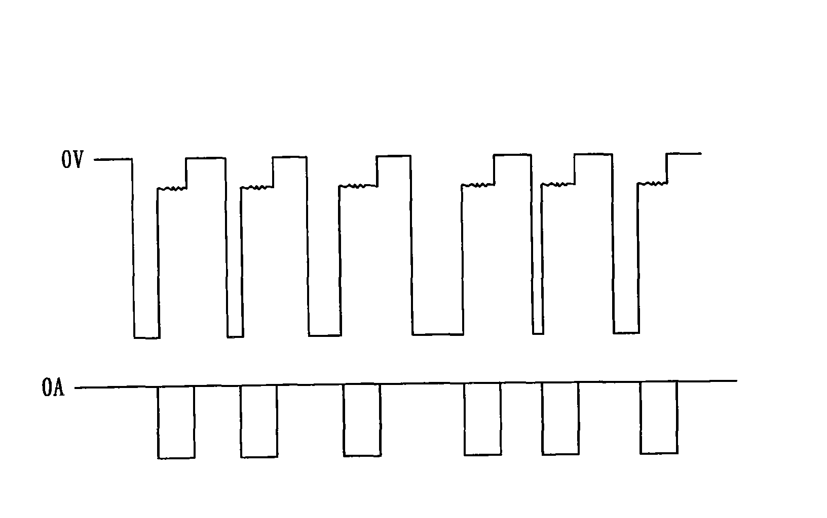
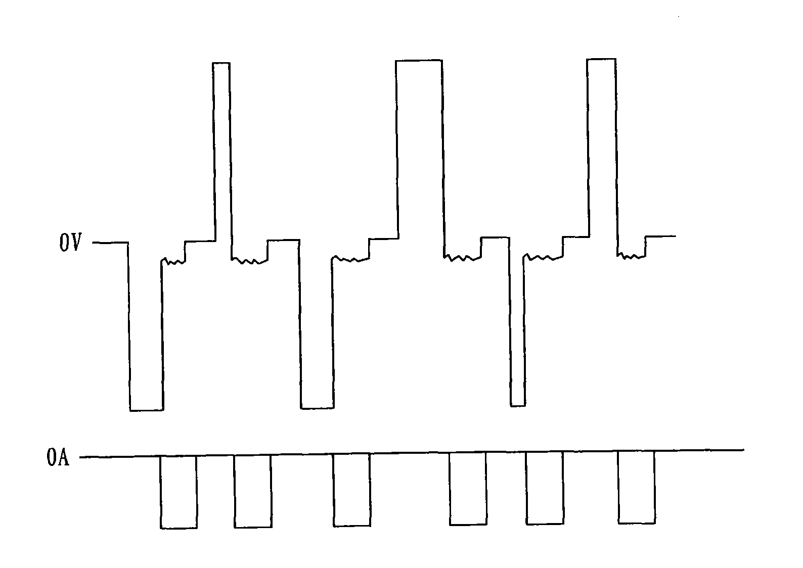
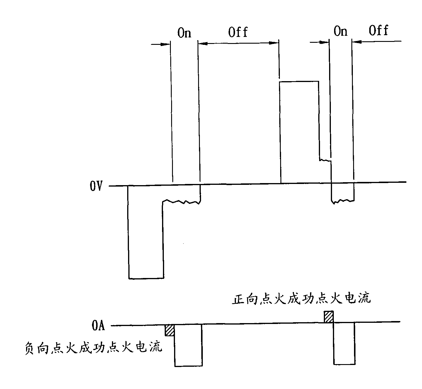
[0006] Based on solving the deficiencies of the above-mentioned known technologies, the present invention is a discharge power source control method and device, the main purpose of which is to propose a method to improve the low-energy discharge machining process, using the existing equal-energy alternating current (AC) discharge power source, It can avoid the problems of poor processing efficiency and large wire loss in the electrolytic discharge power supply in the known technology, and can also take into account the need for the elimination of electrolytic phenomena. Its application can improve the efficiency of micro-wire EDM and reduce wire loss. Part of the repairing process of cutting EDM can also reduce wire loss, and it can also improve the electrolysis problem of deep hole EDM. With a control device, control automation can be achieved. The control device can automatically adjust and respond to the actual processing conditions, and improve Processing efficiency

Method used


Image

  • Method and device for controlling discharging power supply
  • Method and device for controlling discharging power supply
  • Method and device for controlling discharging power supply

Examples


Embodiment Construction

[0042] Now, the detailed structure of the present invention and its connections are described in conjunction with the following drawings, so as to facilitate the understanding of those skilled in the art.

[0043] Currently known EDM pulse control methods are equal-frequency machining control method and equal-energy machining control method, both of which have two operation modes of direct current (DC) and alternating current (AC). The known methods are analyzed and compared as follows:

[0044] (1) Equal frequency control method: the control method uses the switch Qf to turn on and off (On time, Off time) at a fixed time, and the time can be set separately, because the time of on and off is fixed, so it is called equal frequency discharge . The advantage of this method is that the control method is simple, but because the gap state when the switch is turned on is unknown, the actual discharge time length cannot be confirmed, so the discharge energy of a single shot is not fix...


PUM


Abstract

The invention discloses a method and a device for controlling a discharging power supply, and provides a novel method and a novel device for controlling the discharging power supply. The device consists of a bipolar ignition detection module, a discharging module and a micro control unit; the micro control unit is used for controlling an ignition direction and determining a gap state; the presentinterpolar state is detected and an electrolytic phenomenon is eliminated by a bipolar ignition detection discharging method; and in a state suitable for discharging, a discharging and cutting process is performed so as to realize homenergic discharging machining control. In the control method provided by the invention, an ignition detection program is controlled that positive operation can be reused after one or a plurality of negative ignition discharging periods if one positive ignition discharging period is finished; and an average voltage tends to zero. By the invention, the microwire machining efficiency is improved, and electrode loss is reduced; benefits of increasing the machining speed and reducing the used consumable can be achieved; and the linear cutting and discharging machining equipment manufacturing industry in China steps into the fine machining field.

Description

technical field [0001] The present invention relates to a discharge power supply control method and device, in particular to a method for improving the low-energy discharge machining process, using the existing equal-energy alternating current (AC) discharge power supply, which can avoid the poor processing efficiency of the electrolytic discharge power supply in the known technology The problem of large wire loss and the need to eliminate electrolytic phenomena can be taken into account at the same time. Its application can improve the efficiency of micro-wire EDM and reduce wire loss. It can also reduce wire loss and reduce wire loss when repairing parts of wire-cut EDM. The electrolysis problem can also be improved for deep-hole electric discharge machining, and a control device can be used to achieve control automation. The control device can automatically adjust the response to the actual processing situation and improve processing efficiency. Background technique [00...

Claims


Application Information

Patent Timeline
IPC IPC(8): B23H1/02
Inventor 李祥国林洋鑫麦朝创
Owner IND TECH RES INST
Learn More