Laser spot welding assembly method of magnetic circuit system of miniature loudspeaker

A micro-speaker, magnetic circuit system technology, applied in laser welding equipment, welding equipment, metal processing equipment, etc., can solve the problems of unfavorable miniaturization and light weight of micro-speakers, high cost, poor durability, etc. and light weight, improve production efficiency, and reduce volume

Inactive Publication Date: 2011-08-17
TSINGHUA UNIV
View PDF3 Cites 3 Cited by
  • Summary
  • Abstract
  • Description
  • Claims
  • Application Information

AI Technical Summary

Problems solved by technology

[0004] The invention provides a laser spot welding assembly method of a micro-speaker magnetic circuit system to overcome the disadvantages of the prior art, such as high cost, low efficiency, poor durability, large pollution, and unfavorable miniaturization and light weight of the micro-speaker.

Method used


Image

  • Laser spot welding assembly method of magnetic circuit system of miniature loudspeaker
  • Laser spot welding assembly method of magnetic circuit system of miniature loudspeaker
  • Laser spot welding assembly method of magnetic circuit system of miniature loudspeaker

Examples


Embodiment 1

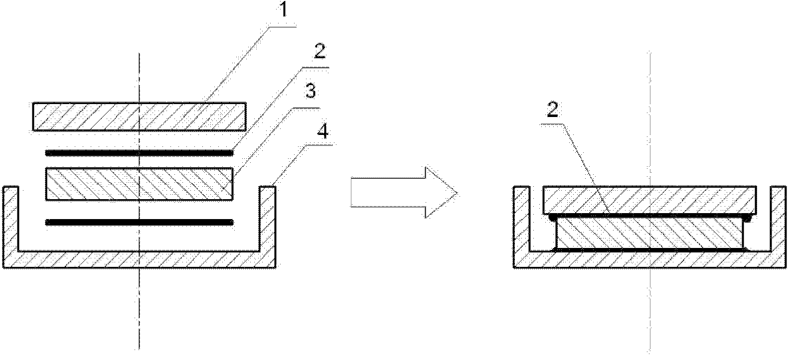
[0039] Such as image 3 , 4 As shown, for the assembly of the magnetic circuit system in which the permanent magnet 3 is circular and has a small radius, a single welding point is arranged at the respective centers of the top plate 1 and the yoke 4 for laser spot welding. Among them, the permanent magnet adopts high-performance sintered NdFeB permanent magnet N48, and the top plate 1 and the yoke 4 adopt common-quality cold-rolled low-carbon steel. Stack the top plate 1, permanent magnet 3 and yoke 4 of the magnetic circuit system in order from top to bottom; fix the stacked parts to be welded on the workbench of the Nd:YAG laser with a fixture, and move the workbench Position the laser head at the spot to be soldered on the top plate 1; turn on the laser and set the parameters of the laser as follows: the peak pulse power is 812.5W, the pulse width is 16ms, the defocus is 0mm, and argon is used as the shielding gas; Argon gas is supplied, and the spot to be welded at the ce...

Embodiment 2

[0042] Such as Figure 5 , 6 As shown, for the assembly of the magnetic circuit system in which the permanent magnet 3 is circular and has a relatively large radius, laser spot welding is performed with 4 welding spots evenly arranged on the circle centered on the respective centers of the top plate 1 and the yoke 4 . Among them, the permanent magnet adopts high-performance sintered NdFeB permanent magnet N48, and the top plate 1 and the yoke 4 adopt common-quality cold-rolled low-carbon steel. Stack the top plate 1, permanent magnet 3 and yoke 4 of the magnetic circuit system in order from top to bottom; fix the stacked parts to be welded on the workbench of the Nd:YAG laser with a fixture, and move the workbench Position the laser head at the spot to be welded on the yoke 4; turn on the laser, and set the parameters of the laser as follows: the pulse peak power is 300W, the pulse width is 10ms, the defocus is 0mm, and nitrogen is used as the shielding gas; Nitrogen gas, we...

Embodiment 3

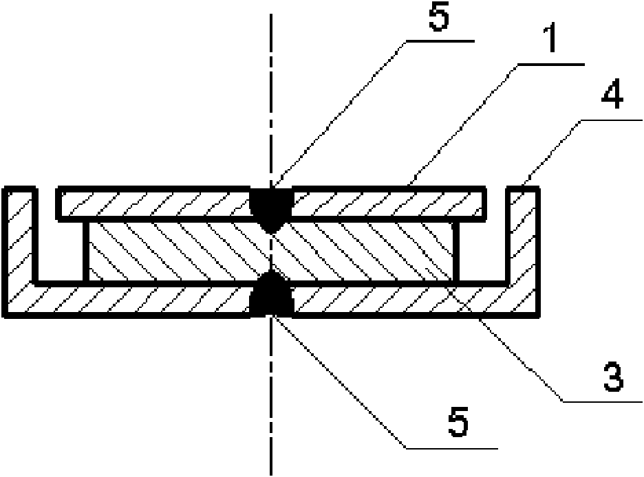
[0045] Such as Figure 9 , 10 As shown, for the assembly of the magnetic circuit system in which the permanent magnet 3 is square, two welding spots are evenly arranged on the long axis of the top plate 1 and the yoke 4 for laser spot welding. Among them, the permanent magnet adopts high-performance sintered NdFeB permanent magnet N48, and the top plate 1 and the yoke 4 adopt common-quality cold-rolled low-carbon steel. Stack the top plate 1, permanent magnet 3 and yoke 4 of the magnetic circuit system in order from top to bottom; fix the stacked parts to be welded on the workbench of the Nd:YAG laser with a fixture, and move the workbench Position the laser head at the spot to be soldered on the top plate 1; turn on the laser, and set the parameters of the laser as follows: the peak pulse power is 1000W, the pulse width is 20ms, the defocus is 3.5mm, and argon is used as the shielding gas; Argon gas is supplied, and the spots to be welded on the top plate 1 are welded in se...


PUM

PropertyMeasurementUnit
poweraaaaaaaaaa

Abstract

The invention relates to a laser spot welding assembly method of a magnetic circuit system of a miniature loudspeaker and belongs to the manufacturing technology field of miniature loudspeakers. Welding spots are reasonably arranged by the adoption of the laser spot welding method according to the dimension and the shape of the magnetic circuit system to realize the one-step forming of the laser spot welding of the magnetic circuit system of the miniature loudspeaker; and a joint is stable and has high efficiency and low cost. After the welding, a top plate, a magnet yoke and a permanent magnet are tightly fitted; and the assembled magnetic circuit system has small volume, and the acoustical property of the magnetic circuit system is basically unchanged. Any substances capable of polluting the environment are not used or discharged during the welding process, so that the working environment is clean. Therefore, the laser spot welding assembly method not only can overcome the defects in the prior art, but also can provides a shortcut for solving the assembly problem of the magnetic circuit system of the miniature loudspeaker.

Description

technical field [0001] The invention relates to an assembly method of a micro-speaker magnetic circuit system, and belongs to the technical field of micro-speaker manufacture. Background technique [0002] Micro speakers usually include three parts: magnetic circuit system, vibration system and support system. The magnetic circuit system is composed of permanent magnets, yokes and top plates, which are used to provide a constant magnetic field. The permanent magnets generally use high-performance sintered NdFeB permanent magnets, and the yokes and top plates generally use low-carbon steel with good magnetic permeability; the vibration system consists of It is composed of bobbin, vibrating diaphragm, damper, dust cover and choke ring; the support system is composed of frame and gasket, and its function is to protect the magnetic circuit system and vibration system. [0003] The assembly of the traditional micro-speaker magnetic circuit system is mainly completed by using adh...

Claims


Application Information

Patent Timeline
Patent Type & Authority Applications(China)
IPC IPC(8): B23K26/22B23K26/42B23K26/70
Inventor 常保华伊晨晖白少俊都东张骅
Owner TSINGHUA UNIV
Why Eureka
Try Eureka