
Inclination-angle-constraint-based kinematic calibration method for Stewart parallel robot

A technology of robot kinematics and robot movement, applied in the field of automation, can solve the problems of destroying passive joint hinges, limited selection space, and affecting the accuracy of calibration results, etc., to avoid dependence on accurate measurement, high degree of automation, and improve pose The effect of precision

Inactive Publication Date: 2011-08-17
XI AN JIAOTONG UNIV
View PDF3 Cites 45 Cited by
  • Summary
  • Abstract
  • Description
  • Claims
  • Application Information

AI Technical Summary

Problems solved by technology

However, it is not easy to install redundant sensors on the passive joint hinges of parallel robots to obtain internal motion information. It needs to be considered in advance in the design stage of the robot, and it cannot be applied to already constructed robotic equipment, and the installation of redundant sensors still needs to be considered Effects on mechanical strength of passive joints
Using a mechanical locking device to impose motion constraints will reduce the freedom of movement at the end of the parallel robot, requiring the drive joints of the robot to have the ability to operate passively and provide motion measurement, so it cannot be applied to many parallel robots driven by "motor + ball screw"
At the same time, the use of a mechanical locking device will greatly reduce the original narrow working space of the parallel robot, which limits the selection space of the calibration measurement configuration, which is not conducive to fully stimulating the structural characteristics of the robot.
In addition, during the calibration process, relying on mechanical locking devices to achieve motion constraints, it is easy to generate a leverage effect between the components and cause deformation, which affects the accuracy of the calibration results in the lightest cases, and may damage the relatively "fragile" passive joint hinges in severe cases

Method used


Image

  • Inclination-angle-constraint-based kinematic calibration method for Stewart parallel robot
  • Inclination-angle-constraint-based kinematic calibration method for Stewart parallel robot
  • Inclination-angle-constraint-based kinematic calibration method for Stewart parallel robot

Examples


Embodiment Construction

[0024] The present invention is described in further detail below in conjunction with accompanying drawing:

[0025] see Figure 1-5 , a Stewart parallel robot kinematics calibration method based on inclination constraints, including the following steps:

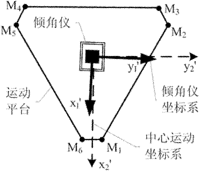
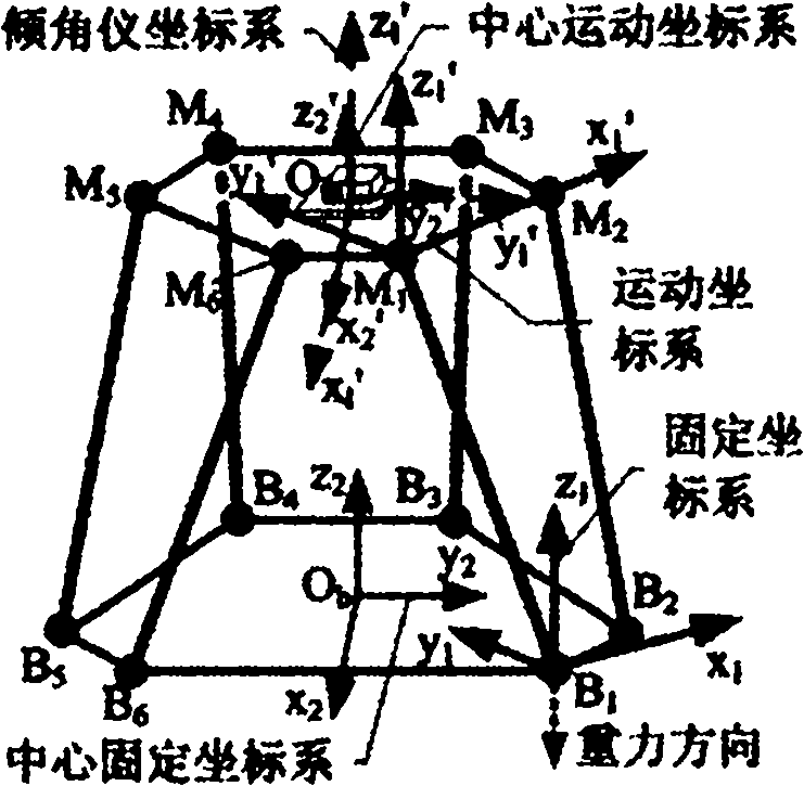
[0026] First, specify how to establish the calibration coordinate system, such as image 3 shown, where:

[0027] Motion coordinate system M 1 -x 1 'y 1 'z 1 ′——take the joint hinge point M on the motion platform 1 as the origin of the coordinate system; x 1 ' axis passes through M 2 point, and along direction; x 1 'y 1 ' plane by M 1 , M 2 and M 6 Three points are determined, and the motion coordinate system is established according to the principle of the right-hand system;

[0028] Center motion coordinate system O m -x 2 'y 2 'z 2 ′—— general M 1 -x 1 'y 1 'z 1 ' around itself z 1 ′ axis rotates 5π / 6 clockwise, and then translates to the nominal geometric center O of the motion platform m get li...


PUM


Abstract

The invention discloses an inclination-angle-constraint-based kinematic calibration method for a Stewart parallel robot. The method comprises the following steps of: firstly, theoretically establishing a novel kinematic constraint, which is an inclination angle constant constraint, namely keeping two inclination angles of a motion platform of the Stewart parallel robot relative to a horizontal plane constant group by group; secondly, using a servo regulating way to physically realize the established kinematic constraint in a high-precision way; thirdly, establishing a calibration model on the basis of a principle of least square according to the kinematic constraint; and finally, identifying a model parameter by solving a nonlinear least square optimizing problem and compensating for the model parameter in a robot control software. By making full use of a characteristic that a repeating precision of a measuring instrument is superior to a position measuring precision of the measuring instrument, the method has the advantages of good calibration effect, simple measurement, high automatism in the calibrating process and the like.

Description

Technical field: [0001] The invention belongs to the field of automation, and relates to a Stewart parallel robot kinematics calibration method, in particular to a calibration method based on inclination constraints. Background technique: [0002] Stewart parallel robots have the advantages of high structural rigidity, strong bearing capacity, good dynamic performance, and small cumulative error, and have been widely used in industrial production, scientific research, and life services. Motion accuracy is an important index to measure the working performance of parallel robots. It is affected by many factors such as manufacturing and installation errors of robot parts, control errors, joint and hinge clearances, thermal deformation, and vibration. Among them, the manufacturing and installation errors of parts are the most important factors affecting the accuracy of the pose (position and attitude) of the end of the parallel robot movement, which can be identified and compens...

Claims


Application Information

Patent Timeline
IPC IPC(8): B25J9/16G05B13/04
Inventor 冯祖仁任晓栋梁恺杨德伟
Owner XI AN JIAOTONG UNIV
Learn More