Method for manufacturing metal shell power supply nameplate based on laser technology

A technology of metal casing and laser technology, applied in printing, anodizing, etc., can solve the problems of cost loss, prolonging the production cycle, easy to fall off, etc., and achieve the effect of reducing direct cost, reducing management cost and simplifying the processing process

Inactive Publication Date: 2011-08-17
MOSO POWER SUPPLY TECH
View PDF7 Cites 5 Cited by
  • Summary
  • Abstract
  • Description
  • Claims
  • Application Information

AI Technical Summary

Problems solved by technology

In the prior art, the nameplates used on the power supply of the metal case are generally printed on paper or silk screen, both of which have their inherent shortcomings. The traditional printed nameplates are all printed on self-adhesive stickers first. Then, when using it, tear off the nameplates one by one and stick them on the power supply casing. On the one hand, this kind of nameplate has poor versatility. Each product needs to design a nameplate separately, and the cost is relatively high, generally between 0.1 yuan and 0.2 yuan. In addition, indirect cost losses are caused by logistics transshipment, warehouse management, financial settlement, etc., and the power supply needs to be waterproof, moisture-proof, corrosion-resistant, and high-temperature resistant, and the printed nameplate is not waterproof or easily

Method used


Image

  • Method for manufacturing metal shell power supply nameplate based on laser technology
  • Method for manufacturing metal shell power supply nameplate based on laser technology
  • Method for manufacturing metal shell power supply nameplate based on laser technology

Examples


Embodiment Construction

[0022] This embodiment is a preferred implementation mode of the present invention, and other principles and basic structures that are the same or similar to this embodiment are within the protection scope of the present invention.

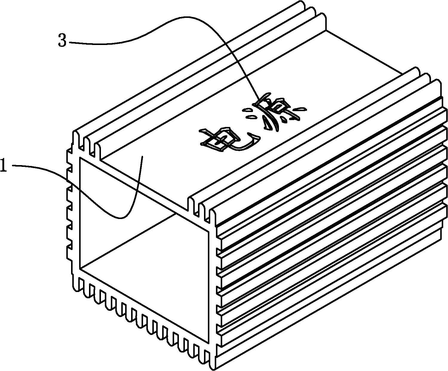
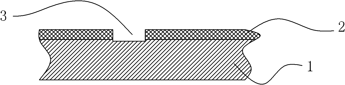
[0023] The present invention uses a laser marking machine to form a nameplate on the metal casing of the power supply by means of laser, which includes the following steps:

[0024] A. Form a layer of film with a color different from that of aluminum on the aluminum casing of the power supply. Since the aluminum casing itself is white, the text pattern formed directly on it by laser laser is not clear enough. In this embodiment, anodic plating is used. A layer of aluminum oxide film is formed on the aluminum casing of the power supply. The usual oxide film is silver gray, and the thickness of the aluminum oxide film is 10μm-18μm. During anodic plating, the plating voltage is 20V-22V, and the plating time is 20min. -40min, in this embodiment, anodi...


PUM


Abstract

The invention discloses a method for manufacturing a metal shell power supply nameplate based on a laser technology. The method comprises the following steps of: A, forming a layer of film with color different from that of aluminum on an aluminum shell of a power supply; and B, forming a laser nameplate pattern on the aluminum shell of the power supply in a laser way by using a laser marking machine according to a preset nameplate shape. By the method, the material of the nameplate is saved; the direct cost is reduced; because the links of material purchase, outsourcing processing, transferring, store management and the like are not required when the nameplate is manufactured by using laser, the management cost is reduced; and production by the method is more advantageous in the present situation of small orders and many machine types, because the method is not controlled by the number of orders and the orders can be carved and printed regardless of the number of the orders. The nameplate manufactured by the invention has waterproofness, moisture resistance, high temperature resistance, simple processing process and low cost, and is not easy to erase. At the same time, materials of a shell of a product are convenient to prepare; to products with different powers or different clients, one part number can be used for material preparation if the size of the shells is the same, so the method is relatively high in flexibility.

Description

technical field [0001] The invention discloses a method for making a nameplate, in particular to a method for making a nameplate for a metal shell power supply based on laser technology. Background technique [0002] The nameplate is mainly used to record the technical data of the product and some information such as the manufacturer, which is an indispensable thing for a product. The current power supply products such as switching power supplies are usually made of metal shells. On the one hand, they have good heat dissipation, and on the other hand, they are convenient to prepare materials. They can be cut into long strips of aluminum profiles that are processed according to the required length. In the prior art, the nameplates used on the power supply of the metal case are generally printed on paper or silk screen, both of which have their inherent shortcomings. The traditional printed nameplates are all printed on self-adhesive stickers first. Then, when using it, tear ...

Claims


Application Information

Patent Timeline
IPC IPC(8): B41J2/455C25D11/04
Inventor 顾永德苏周柳安董洁
Owner MOSO POWER SUPPLY TECH
Why Eureka
Try Eureka