
Low-noise axial plunger pump based on average pressure

An axial plunger pump and pressure technology, which is applied in the direction of pumps, multi-cylinder pumps, liquid variable displacement machines, etc., can solve the problems of positive and negative overshoot of plunger chamber pressure, pressure shock, cavitation and other problems, and achieve The effect of increasing the effective oil suction and discharging stroke, reducing the rotational torque of the swash plate, and increasing the average outlet flow

Active Publication Date: 2011-08-17
ZHEJIANG UNIV
View PDF6 Cites 17 Cited by
  • Summary
  • Abstract
  • Description
  • Claims
  • Application Information

AI Technical Summary

Problems solved by technology

If the mismatch angle is too large, the pre-boost and pre-depressurization time of the plunger chamber will be too long, which will cause positive and negative overshoot of the plunger chamber pressure, resulting in pressure shock and cavitation
[0005] 3. Damping hole: The damping hole can be regarded as a damping groove with a constant cross-sectional area. The effect on the pressure transition of the plunger cavity is the same as that of the damping groove. In order to achieve the same flow distribution effect as the damping groove, a stepped hole structure can be used. Realize the gradual increase of the throttle area, but the research and test results show that it is not as effective as the damping groove in reducing pressure shock and flow pulsation
[0007] To sum up, the existing flow distribution structure is not only sensitive to the working parameters of the axial piston pump, but also reduces the average outlet flow and volumetric efficiency

Method used


Image

  • Low-noise axial plunger pump based on average pressure
  • Low-noise axial plunger pump based on average pressure
  • Low-noise axial plunger pump based on average pressure

Examples


Embodiment Construction

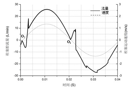
[0015] The plunger chamber moves for one week, and there are two flow backflows, figure 2 It is a typical axial piston pump plunger cavity flow change curve. The upper and lower dead centers at zero speed are the dividing points of oil suction and oil discharge. The flow opposite to the speed is flow backflow. Among them, the flow backflow peak value from the high-pressure oil discharge waist groove to the low-pressure plunger cavity determines the peak value of the plunger pump outlet flow pulsation, and also reduces the effective oil discharge capacity of the plunger pump. From the high-pressure plunger cavity to the low-pressure oil suction waist The backflow of the flow of the groove converts the pressure energy into energy dissipation, which is a kind of internal leakage. The flow distribution structure of the present invention directly connects the plunger cavity near the upper and lower dead centers, and the oil liquid flows from the bottom dead center Near the high ...


PUM


Abstract

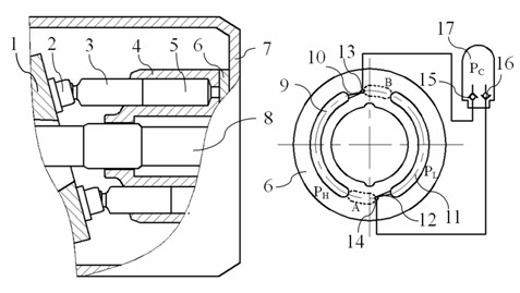
The invention discloses an axial plunger pump based on average pressure. The axial plunger pump comprises an inclined disk, a plurality of piston shoes, a plurality of plungers, a cylinder body, a flow distributor, a shell, a main shaft, a rear check valve, a front check valve and a pressure recovery containing chamber; after a high-pressure plunger chamber finishes oil discharging and enters the transition region of the flow distributor, the high-pressure oil in the plunger chamber flows into a pressure recovery containing chamber through the front check valve; and the high-pressure plunger chamber reduces pressure in advance, the pressure of the pressure recovery containing chamber increases, while a low-pressure plunger chamber finishes the oil absorption and enters the transition region of the flow distributor, the high-pressure oil liquid stored in the pressure recovery containing chamber flows into the low-pressure plunger chamber through the rear check valve, the low-pressure plunger chamber increases the pressure in advance, and pressure of the pressure recovery containing chamber reduces. Under the effect of average pressure, the boost in advance and depressurization effect of the plunger chamber are approximately equal to half of the pressure difference of a high-pressure oil extraction kidney slot and a low-pressure oil absorption kidney slot of the axial plunger pump, the outlet flow rate pulsation of the axial plunger pump is reduced, the rotation torque of the inclined disk is reduced, and the average flow rate of the pump outlet is increased.

Description

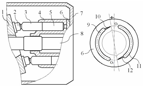
technical field [0001] The invention relates to an axial plunger pump, in particular to a low-noise axial plunger pump based on pressure averaging. Background technique [0002] Due to the advantages of high working pressure, high power density, and convenient variable control, axial piston pumps are the most widely used core power components in hydraulic transmission systems, but they also have significant disadvantages such as high noise. As a major theme of the industry, the requirement to reduce the working noise level of axial piston pumps is becoming increasingly urgent. The noise of the axial piston pump is divided into structure noise and fluid noise, which are mainly caused by the pressure shock of the plunger chamber and the flow pulsation of the pump outlet respectively. Flow pulsation. Such as figure 1 As shown, the plunger reciprocates in the cylinder bore to realize the oil suction and oil discharge of the axial piston pump. If the plunger chamber is connect...

Claims


Application Information

Patent Timeline
IPC IPC(8): F04B1/22
Inventor 徐兵张军辉杨华勇
Owner ZHEJIANG UNIV
Learn More