Rotor of built-in permanent magnet motor and magnetic steel structural parameter determining method thereof

A permanent magnet motor, built-in technology, applied in the shape/style/structure of the magnetic circuit, rotating parts of the magnetic circuit, etc., can solve the performance indicators affecting the torque ripple, vibration and noise efficiency of the motor, and the difficulty of the maximum safe running speed of the motor. The problems such as the increase of air gap flux density and the difficulty of adjusting the sine degree of the waveform to achieve the effect of increasing the maximum safe running speed, reducing the radial thickness and reducing the moment of inertia

Inactive Publication Date: 2011-08-17
SHANGHAI UNIV
View PDF4 Cites 31 Cited by
  • Summary
  • Abstract
  • Description
  • Claims
  • Application Information

AI Technical Summary

Problems solved by technology

However, when running at high speed, the conventional permanent magnet motor with built-in rotor structure also has obvious shortcomings. Taking the "I" type built-in rotor as an example, the main performances are as follows: 1) Due to the long moment arm of the rotor centrifugal force distribution load, the large The bending moment causes a large stress at the magnetic isolation bridge and a large deformation at the middle position of the adjacent magnetic isolation bridge, and the stress and deformation increase rapidly with the increase of the rotational speed
Restricted by the yield strength of the rotor silicon steel sheet and the length of the air gap of the motor, it is difficult to increase the maximum safe operating speed of the motor; 2) The sine degree of the air gap flux density waveform is difficult to adjust, and the harmonic component is large, which affects the torque ripple of the motor, Vibration, noise, efficiency and other performance indicators; 3) The structural and magnetic reasons restrict the minimum size of the silicon steel sheet, and the radial thickness of the rotor is relatively large, which increases the weight and moment of inertia of the rotor
Therefore, surface-mounted and conventional built-in rotor structure permanent magnet motors are difficult to meet the requirements of the drive system for motors under high-speed operating conditions

Method used


Image

  • Rotor of built-in permanent magnet motor and magnetic steel structural parameter determining method thereof
  • Rotor of built-in permanent magnet motor and magnetic steel structural parameter determining method thereof
  • Rotor of built-in permanent magnet motor and magnetic steel structural parameter determining method thereof

Examples


Embodiment 1

[0049] The high-quality high-speed built-in 4-pole permanent magnet motor rotor includes a rotor core (3) and a magnetic steel (1) built into it, and is characterized in that:

[0050] (1) The magnetic steel (1) of each pole is composed of odd-numbered magnetic steels of the same polarity;

[0051](2) The odd-numbered magnets of each pole are respectively built into the rotor core (3) along the rotor circumference; the centerline of the middle section of the magnet coincides with the centerline of the pole, and the remaining even-numbered magnets are symmetrically distributed on both sides. The size of the magnetic steel at the laterally symmetrical position is the same; a reinforcing rib (2) with a magnetic isolation effect is arranged between each adjacent two sections of the magnetic steel;

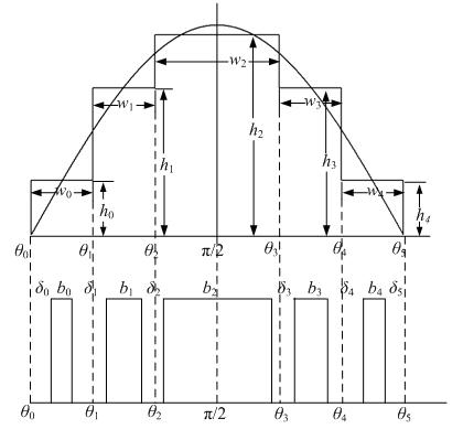
[0052] (3) The width of the magnets (1) with odd numbers of poles is modulated and determined according to the principle of the sinusoidal distribution of the air-gap magnetic density ...

Embodiment 2

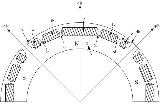
[0055] This embodiment is basically the same as Embodiment 1, and the feature is that the magnetic poles are divided into 5 sections. Compared with the conventional structure, each pole is composed of 5 sections of magnetic steel (1a, 1b, 1c, 1d, 1e) of the same polarity, which are respectively built into the rotor core (3) along the circumference of the rotor, and the middle section of magnetic steel (1c ) coincides with the pole centerline, the magnets (1b, 1d) and the magnets (1a, 1e) are symmetrically distributed on both sides of the magnet (1c), the magnets (1b) and the magnets (1d), magnets The steel (1a) and the magnetic steel (1e) have the same size, and magnetic isolation reinforcing ribs (2a, 2b, 2c, 2d) are arranged between each section of the magnetic steel, and the distance between the magnetic steel (1a, 1e) and the outer circle of the rotor There are magnetic isolation bridges (4a, 4b) between them, and there are gaps between them and adjacent magnetic poles of ...


PUM


Abstract

The invention relates to a rotor of a high-quality and high-speed built-in permanent magnet motor and a magnetic steel structural parameter determining method thereof. In the invention, the whole section magnetic steel of each electrode of the rotor of a conventional built-in permanent magnet motor is divided into multiple sections of magnetic steel which have the same polarity and different widths; the multiple sections of the magnetic steel are respectively arranged in a rotor core; and reinforcing ribs with the function of magnetic isolation are arranged among the multiple sections of the magnetic steel. By reasonably modulating and determining the width and distribution of each section of the magnetic steel, the air gap magnetic density waveform approaches sine distribution; harmonic components are reduced to the greatest extent; the eddy current loss of the magnetic steel and the torque pulsation of the motor are simultaneously reduced; and the electromagnetic performance of the motor is enhanced. Furthermore, the multiple sections of the magnetic steel are arranged in the circumference along the rotor; the highest rotating speed of the safe operation of the rotor is greatly enhanced on machinery; the radial thickness which is needed by the magnetic circuit of the rotor is obviously reduced on the structure; the rotational inertia and weight of the rotor are reduced; the dynamic response of the motor is improved; and the requirements of a high-speed driving system on the performance of the motor are met.

Description

technical field [0001] The invention relates to a rotor of a built-in permanent magnet motor, in particular to a high-quality high-speed built-in permanent magnet motor rotor and a method for determining its magnetic steel structure parameters. Background technique [0002] With the rapid development of industrial technology and permanent magnet materials, built-in permanent magnet motors have increasingly broad application prospects in high-speed servo systems such as precision CNC machine tools, machining centers, and industrial robots. At the same time, more stringent requirements are put forward for the mechanical and electromagnetic performance of the interior permanent magnet motor. It is necessary to pursue high stiffness, small inertia, and light weight to meet the requirements of high dynamic response and high power / torque density of the system; it is also necessary to suppress the harmonic components in the air-gap magnetic field to achieve low torque ripple and lo...

Claims


Application Information

Patent Timeline
Patent Type & Authority Applications(China)
IPC IPC(8): H02K1/27
Inventor 黄苏融张琪陈益辉张诗香王凯立谢国栋
Owner SHANGHAI UNIV
Why Eureka
Try Eureka