Method and system for recovering high-temperature sensible heat of molten blast furnace slag

A blast furnace slag and high temperature technology, which is applied in the field of recovering high temperature sensible heat of molten blast furnace slag, can solve the problem of high equipment processing capacity, high temperature resistance, wear resistance and adjustment ability, unfavorable equipment energy consumption and waste heat recovery rate, and recovery of blast furnace slag waste heat Difficulty and other problems, to achieve the effect of saving drying energy consumption, reducing the power consumption of the circulation system, and the particle size

Active Publication Date: 2011-08-24
HANGZHOU BOILER GRP CO LTD
View PDF3 Cites 52 Cited by
  • Summary
  • Abstract
  • Description
  • Claims
  • Application Information

AI Technical Summary

Problems solved by technology

It is very difficult to recover the waste heat of blast furnace slag, and there are many technical difficulties, such as: large discharge of blast furnace slag, high temperature, discontinuity, high requirements on equipment processing capacity, temperature resistance, wear resistance and adjustment ability; in order to produce qualified building materials Alternative materials require fast cooling speed, but rapid cooling has adverse effects on equipment energy consumption and waste heat recovery rate
Therefore, although there are many studies on the recovery of high-temperature sensible heat of blast furnace slag at home and abroad, only the cooling drum method, wind quenching method and centrifugal granulation method have been industrially tested, and there is no successful case of actual industrial application.

Method used


Image

  • Method and system for recovering high-temperature sensible heat of molten blast furnace slag
  • Method and system for recovering high-temperature sensible heat of molten blast furnace slag

Examples


Embodiment

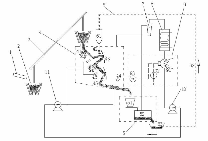
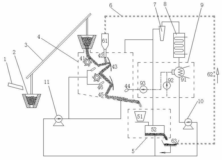
[0038] As shown in the figure, the high temperature sensible heat recovery system for molten blast furnace slag consists of blast furnace slag ditch 1, slag hopper 2, slag hopper lifting mechanism 3, rapid cooling unit 4, slow cooling unit 5, cold slag particle circulation unit 6, cyclone dust collector 7, It is composed of waste heat boiler 8, condensing unit 9, circulation fan 10 and pressurization fan 11.

[0039] Specifically, the blast furnace slag ditch 1 is usually a part of the structure of the blast furnace itself, and is a channel for blast furnace slag discharged from the blast furnace. The slag hopper 2 is made of refractory material and holds the liquid high-temperature blast furnace slag flowing out of the blast furnace slag ditch 1; in order to ensure the fluidity of the slag, the slag hopper 2 is equipped with a heating and heat preservation device; in order to reduce the waiting time between two slag discharges, The flow rate of slag treatment is stabilized so...


PUM


Abstract

The invention discloses a method and a system for recovering high-temperature sensible heat of molten blast furnace slag. The system comprises a blast furnace slag runner, a slag hopper, a slag hopper lifting mechanism, a quenching unit, a slow cooling unit, a cold slag particle circulation unit, a cyclone dust collector, a waste heat boiler, a condensing unit, a circulating fan, and a booster fan. The method for recovering waste heat comprises the following steps of: crushing and quickly cooling the molten blast furnace slag in the quenching unit in a composite way of a rotary crushing wheel, high-pressure cold air, a slag trap, cold slag particles and cooling water, and fully exchanging heat with solidified blast furnace slag in the slow cooling unit by using cooling air; and allowing high-temperature air which comes out of the quenching unit and the slow cooling unit to enter the waste heat boiler and performing heat exchange, transforming into steam or electric power and then outputting. The subsequent utilization of blast furnace slag and the waste heat recovery efficiency are synchronously considered, condensed water is recycled, finished slag does not contain water or only contains a small amount of water, the granulation effect of the slag is better, and the contradiction between intermittent slagging and continuous heat production of blast-furnace ironmaking is resolved.

Description

technical field [0001] The invention belongs to the technical field of iron and steel metallurgy energy saving and emission reduction, and secondary energy recovery, and in particular relates to a method and system for recovering high-temperature sensible heat of molten blast furnace slag. Background technique [0002] The position of steel as an important structural and functional material will not change significantly in the foreseeable time frame. The iron and steel industry is a resource-, capital-, and technology-intensive industry, covering a series of projects such as geology, mining, ore dressing, ironmaking, steelmaking, rolling, and metal products. It is a complex of production, management, technology, and economy. No matter in the past and present, or in a long historical period in the future, the development level of the iron and steel industry is still one of the important symbols to measure the level of a country's industrialization and modernization. In March...

Claims


Application Information

Patent Timeline
Patent Type & Authority Applications(China)
IPC IPC(8): C21B3/08C21B7/14F27D17/00
CPCC21B2400/024C21B2400/052C21B2400/056C21B2400/062C21B2400/072C21B2400/08Y02P10/25
Inventor 周勇颜飞龙赵剑云侯晓东
Owner HANGZHOU BOILER GRP CO LTD
Why Eureka
Try Eureka