Device and method for simulating dynamic flame and simulated carbon bed

A technology for simulating flame and simulating carbon, which is applied in the field of devices for simulating dynamic flame and simulating carbon bed, can solve the problems of discontinuous change of flame, sudden opening and closing of illuminants, and insufficient fidelity of the carbon bed, and achieves continuous and realistic flickering of the carbon bed, The effect of reducing the number of point light sources and increasing the height of the simulated flame

Inactive Publication Date: 2011-08-24
宁波高博科技有限公司
View PDF7 Cites 4 Cited by
  • Summary
  • Abstract
  • Description
  • Claims
  • Application Information

AI Technical Summary

Problems solved by technology

[0003] These three types of devices have their own advantages and disadvantages, but the first and second types require the use of blowers or motors, and the products are noisy, thick, and bulky.
Although the third category solves the problems of the first two categories, its main problems are: 1. The shape of the flame is mainly determined by the hardware. Once the shape of the main flame needs to be changed, the hardware must be changed; The change is discontinuous; 3. The main illuminant emits light continuously or at high frequency,

Method used


Image

  • Device and method for simulating dynamic flame and simulated carbon bed
  • Device and method for simulating dynamic flame and simulated carbon bed
  • Device and method for simulating dynamic flame and simulated carbon bed

Examples


Embodiment 1

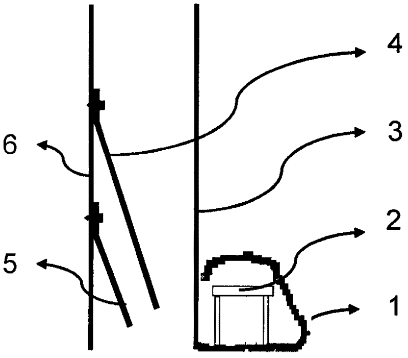
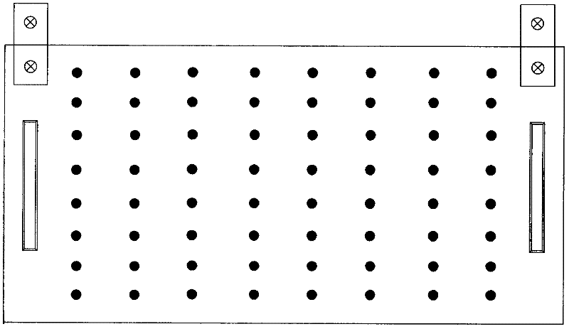
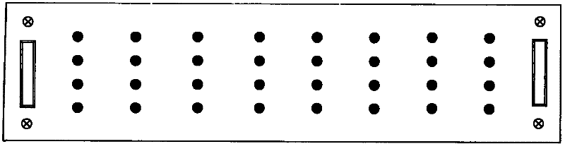
[0059] See Figure 1 to Figure 13 As shown, the device for simulating dynamic flames and simulating carbon beds provided in this embodiment includes a simulating carbon bed 1 that can transmit light on the top and sides, a carbon bed light source that is arranged in the simulating carbon bed 1, an imaging screen 3, Flame template 4, simulated flame light source and backboard 6, and electrical control devices for controlling the power supply voltage and power supply time of each illuminant in the carbon bed light source and the simulated flame light source ( figure 1 not shown). The imaging screen 3 is located inside the simulated carbon bed 1 . The flame template 4 is arranged between the simulated flame light source and the imaging screen 3 . Both the carbon bed light source and the simulated flame light source use a point light source array, and the power supply between the illuminants in the point light source array is independent of each other; and the illuminants in the...

Embodiment 2

[0077] Different from Embodiment 1, the simulated carbon bed 1 and its built-in carbon bed light source circuit board 2 are placed between the imaging screen 3 and the flame template 4, and the structure and pattern of the flame template are different from Embodiment 1. See Figure 14 , Figure 15 shown.

Embodiment 3

[0079] The difference from the second embodiment is that the simulated flame light source circuit board 5 is placed parallel to the back plate 6 and directly riveted or screwed on the back plate 6 sprayed with insulating paint, and the wide-angle light-emitting diode 8 is directly welded in an S shape on the simulated On the flame light source circuit board 5 and at an angle of 10 to 80 degrees with the simulated flame light source circuit board 5, the flame template 4 is parallel to the imaging screen 3 and the back plate 6 and is directly fixed on the back plate 6 by a metal bracket 7, see Figure 16 , Figure 17 shown.


PUM

PropertyMeasurementUnit
Thicknessaaaaaaaaaa

Abstract

The invention relates to a device for simulating dynamic flame and a simulated carbon bed. The device comprises a simulated flame light source, an imaging screen, a flame template, the simulated carbon bed and a carbon bed light source, wherein the flame template is arranged between the simulated flame light source and the imaging screen; at least the top and the lateral surface of the simulated carbon bed can transmit light, and the simulated carbon bed is placed in front of the imaging screen or between the imaging screen and the flame template; and the carbon bed light source is placed in the simulated carbon bed. The device is characterized in that: point light source arrays are adopted in the carbon bed light source and the simulated flame light source, and power supplies among the luminous bodies in the point light source arrays are independent with one another; and the device for simulating the dynamic flame and the simulated carbon bed also comprises an electric control devicefor controlling the magnitude of power supply voltage and the power supply time of each luminous body in the carbon bed light source and the simulated flame light source. Compared with the prior art,the device has the advantages of simple structure, no noise, low thickness, light weight, energy conservation, environment friendliness, long service life, strong third dimension of the simulated flame, easily changed flame shape and size and more vivid form.

Description

technical field [0001] The invention relates to a device and method for simulating dynamic flames and simulating carbon beds in electric fireplaces, murals, and decorative wall lamps, in particular to a device and method capable of realizing highly realistic simulations of dynamic flames and simulating carbon beds during combustion device. Background technique [0002] There are three main types of traditional flame simulation methods: 1. Air flow type, using light to illuminate the red silk blown by the blower to simulate dynamic flames; 2. Mechanical transmission type, the motor drives the rotation of the drum engraved with light-transmitting holes, and the light projects through the drum On the imaging screen, such as the Chinese patent No. ZL01113160.8, which imitates the flame burning image device, or the irregular reflection of light on the reflective brush bar driven by the motor to generate a flickering flame image, such as the imitation flame burning image of the US...

Claims


Application Information

Patent Timeline
IPC IPC(8): F21S10/04H05B37/02
CPCY02B20/42Y02B20/40
Inventor 刘安玲袁媛孙利平杨军
Owner 宁波高博科技有限公司
Why Eureka
Try Eureka