A dead time control circuit used in a DC-DC converter

A dead time control, DC-DC technology, applied in the field of electronics, can solve problems such as long dead time, and achieve the effect of improving efficiency, reducing size and improving efficiency

Active Publication Date: 2011-08-31
UNIV OF ELECTRONICS SCI & TECH OF CHINA
View PDF4 Cites 27 Cited by
  • Summary
  • Abstract
  • Description
  • Claims
  • Application Information

AI Technical Summary

Problems solved by technology

[0006] The purpose of the present invention is to solve the problem of long dead time in the existing DC-DC converter, and propose a dead time control circuit for DC-DC converter

Method used


Image

  • A dead time control circuit used in a DC-DC converter
  • A dead time control circuit used in a DC-DC converter
  • A dead time control circuit used in a DC-DC converter

Examples


Embodiment Construction

[0015] The present invention will be further elaborated below in conjunction with the accompanying drawings and specific embodiments.

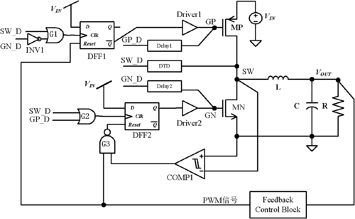
[0016] The structure schematic diagram of the dead time control circuit for DC-DC converter of the present invention is as follows: figure 2 As shown, it specifically includes the first OR gate G1, the second OR gate G2, the first D flip-flop DFF1, the second D flip-flop DFF2, the first NAND gate G3, the first delay unit Delay1, the second delay unit Delay2, The first dead time detector DTD, the first inverter INV1, the first comparator COMP1, the P-type power transistor MP, the N-type rectifier transistor MN, the first drive unit Driver1 and the second drive unit Driver2, wherein the The gate of the P-type power transistor MP is connected to the input end of the first delay unit Delay1, and the output end of the first delay unit Delay1 is connected to an input end of the second OR gate G2; the drain electrode of the P-type power transistor M...


PUM


Abstract

The invention discloses a dead time control circuit used in a DC-DC converter. In allusion to unnecessary power loss brought by conduction loss and reverse recovery in the DC-DC converter, the dead time control circuit used in the DC-DC converter enables a body diode conduction to be detected quickly along the two edges of PWM signal through a dead time detector, thereby turning off a power tube or a rectifying tube to make the body diode conduction time be reduced to be close to the transmission delay time of a drive unit, reducing the power loss brought by the body diode conduction substantially and improving efficiency substantially. The improved efficiency brought by employing the structure enables a higher switch frequency to be feasible, thereby reducing the size of a passive device. Moreover, the circuit of the invention can adjust the dead time adaptively in accordance with different load currents.

Description

technical field [0001] The invention belongs to the field of electronic technology, in particular to a dead-time control circuit used for a DC-DC converter in a power integrated circuit. Background technique [0002] High-efficiency DC-DC converters are often required in battery-powered portable devices, and it is desirable to maximize the time interval between charges. The higher the frequency, the smaller the size of the passive components, so it is generally preferred to use high frequency switching converters. Due to its high efficiency, the synchronous Buck converter is widely used in portable devices. [0003] A typical Buck converter circuit, such as figure 1 shown. In a typical buck circuit mode, the source of the P-type power transistor is connected to the input signal Vin, the gate is connected to the control signal GP, and the drain (SW) is connected to the inductor L, the drain of the N-type rectifier and the negative terminal of the comparator respectively. ...

Claims


Application Information

Patent Timeline
Patent Type & Authority Applications(China)
IPC IPC(8): H02M3/155
Inventor 甄少伟罗萍杨康赵越张波
Owner UNIV OF ELECTRONICS SCI & TECH OF CHINA
Why Eureka
Try Eureka