Low-voltage direct-current controlled continuous flow cell electrofusion chip

A technology of electrofusion and cells, which is applied in the direction of hybrid cell preparation, stress-stimulated microbial growth methods, biochemical equipment and methods, etc., which can solve the problems of low cell fusion efficiency, adverse effects of cell activity and aseptic operation, and complex fusion systems and other issues, to achieve the effect of improved anti-interference, reduced requirements for power signal equipment, and low system cost

Inactive Publication Date: 2011-09-07
CHONGQING UNIV
View PDF6 Cites 15 Cited by
  • Summary
  • Abstract
  • Description
  • Claims
  • Application Information

AI Technical Summary

Problems solved by technology

This method provides a new idea for the realization of continuous flow cell operation, and is expected to solve the problems of low cell fusion efficiency and complex fusion system.
However, in this method, the use of high voltage and large electrodes adversely affects cell viability and aseptic handling

Method used


Image

  • Low-voltage direct-current controlled continuous flow cell electrofusion chip
  • Low-voltage direct-current controlled continuous flow cell electrofusion chip
  • Low-voltage direct-current controlled continuous flow cell electrofusion chip

Examples


Embodiment Construction

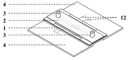
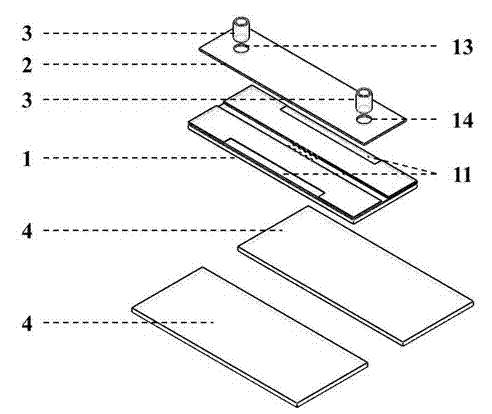
[0038] see figure 1 with figure 2 The continuous flow microelectrode array cell electrofusion chip is composed of a substrate 1 , a cover sheet 2 , a sample inlet and outlet conduit 3 connecting internal and external flow paths, and a metal support sheet 4 .

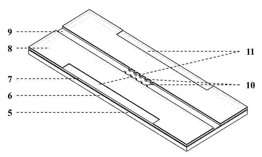
[0039] The structure of the substrate 1 of the chip is shown in image 3 , using silicon material, from bottom to top consists of silicon base layer 5, silicon dioxide insulating layer 6, low-resistance silicon electrode layer 7 and silicon dioxide protective film 8, using micro-processing technology on the low-resistance silicon electrode layer 7 Etching grooves to the silicon dioxide insulating layer 6 forms microchannels 9, the microchannels 9 on both sides are linear, and the microchannels in the middle area are distributed with a series of comb-shaped microelectrodes 10 on both sides of the channel. The micro-electrodes in the shape of a micro-electrode are formed by protruding from the low-resistance silicon ele...


PUM

PropertyMeasurementUnit
depthaaaaaaaaaa
widthaaaaaaaaaa
widthaaaaaaaaaa

Abstract

The invention provides a microelectrode array chip which can be used for continuous flow cell electrofusion. The chip consists of three layers, namely a substrate, a cover plate and a metal supporting piece, wherein the substrate is provided with a microchannel for cell suspension to continuously flow and a microelectrode array for electrically stimulating cells; and the microelectrode array is engraved on the two sides of the microchannel, is connected with the metal supporting piece by a metal lead through a micropore, and is connected with a direct-current power supply through a wire to lead in an electrical signal. The microelectrode array chip has a simple structure and is provided with a small number of microelectrodes, so that processing difficulty is far lower than that of a high-density microelectrode cell electrofusion chip; the required fusion voltage is direct-current low voltage, the requirement on equipment is low, and device cost is far lower than that of the conventional cell electrofusion method; meanwhile, cell fusion is continuously performed in the process that cell pairs flow through the microchannel, fusion yield is also far higher than that of the conventional cell electrofusion method, so that the popularization and application of the microelectrode array chip are facilitated.

Description

technical field [0001] The invention relates to biological cell electric fusion technology. Specifically, it relates to a chip device that can realize continuous cell fusion under the condition of low-voltage direct current signal, including microchannel and microelectrode design, cell injection, uniform flow of cells, cell electroporation and fusion, and collection of fused cells. Background technique [0002] The cell fusion method originated from animal cell research. In 1962, Japanese scholar Yoshio Kuda used UV-inactivated Sendai virus to induce the fusion of Ehrlich ascites tumor cells in vitro, realizing the artificial cell fusion method for the first time. However, the yield of virus-induced cell fusion is extremely low, and it is difficult to meet the growing research and application needs. Scientists began to seek better fusion induction methods. In 1974, Chinese-Canadian scientist Gao Guonan discovered that polyethylene glycol (PEG) could promote the fusion of p...

Claims


Application Information

Patent Timeline
Patent Type & Authority Applications(China)
IPC IPC(8): C12M1/42C12N15/02
CPCC12M35/02
Inventor 杨军黄小玲郑小林胡宁侯文生罗洪艳曹毅杨静
Owner CHONGQING UNIV
Why Eureka
Try Eureka