Device for measuring point source stray light transmission coefficient in large dynamic range

A technology with large dynamic range and transmission coefficient, which is applied in the direction of testing optical performance, etc., and can solve problems such as system failure, image quality degradation, and harmful effects of the optical system

Inactive Publication Date: 2011-09-07
HARBIN INST OF TECH
View PDF4 Cites 16 Cited by
  • Summary
  • Abstract
  • Description
  • Claims
  • Application Information

AI Technical Summary

Problems solved by technology

[0003] The impact of stray light on the optical system is very harmful. It is directly manifested in reducing the contrast of the image plane, reducing the signal-to-noise ratio, and may produce spots on the image plane, resulting in a decrease in image quality. In some cases, it may even cause system damage. fail

Method used


Image

  • Device for measuring point source stray light transmission coefficient in large dynamic range
  • Device for measuring point source stray light transmission coefficient in large dynamic range
  • Device for measuring point source stray light transmission coefficient in large dynamic range

Examples


specific Embodiment approach 1

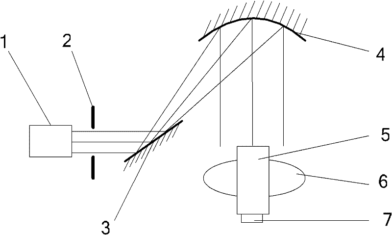
[0011] Specific implementation mode one: combine figure 1 and figure 2 Describe this embodiment, the large dynamic range point source stray light transmission coefficient measuring device in this embodiment includes solar simulator 1, optical path assembly, horizontal turntable 6 and detector; The horizontal turntable 6 described above is used to control the rotation of the optical system 5 to be measured in the horizontal plane; the optical path assembly includes the aperture stop 2, the folding axis mirror 3 and the large-aperture collimator 4; the light emitted by the solar simulator 1 passes through the aperture stop 2 is projected on the refracting mirror 3, and after being reflected by the refracting mirror 3, it is projected onto the large-diameter collimator 4. The light beam emitted by the large-diameter collimator 4 is a large-diameter parallel light. On the entrance pupil aperture of the optical system to be measured 5, that is, the large-diameter collimator 4 exp...

specific Embodiment approach 2

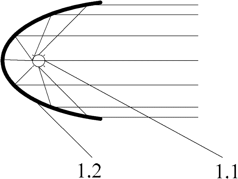
[0012] Specific implementation mode two: combination image 3 Describe this embodiment, the difference between this embodiment and the specific embodiment is that the solar simulator 1 is composed of a high-voltage short-arc xenon lamp 1.1 and an ellipsoidal reflector 1.2; the high-voltage short-arc xenon lamp 1.1 is placed at the focus of the ellipsoidal reflector 1.2 superior. The high-voltage short-arc xenon lamp 1.1 is a high-voltage short-arc xenon lamp with a power of 1000kw and a color temperature of about 6000k. The solar simulator 1 simulates the real sunlight environment, and the divergence angle of the parallel light emitted is less than 32', and the beam uniformity is better than 2.5%. The irradiance at the entrance pupil aperture of the optical system 5 to be tested is greater than 1000 lx. Other compositions and connection methods are the same as those in Embodiment 1.

specific Embodiment approach 3

[0013] Embodiment 3: The difference between this embodiment and Embodiment 1 or 2 is that the horizontal turntable 6 uses a stepping motor to control the rotation, and the rotation angle accuracy is 0.05°. Other compositions and connection modes are the same as those in Embodiment 1 or 2.


PUM


Abstract

The invention discloses a device for measuring point source stray light transmission coefficient in large dynamic range, belonging to the field of photoelectric test and obtaining stray light transmission coefficient in existing optical system. A horizontal turntable of the device is equipped with an optical system to be measured and is used for controlling the optical system to be measured to rotate within a horizontal plane; optical components include an aperture diaphragm, a coude reflector and a large-caliber collimator tube; light emitted by a sun simulator is projected onto the coude reflector via the aperture diaphragm and then projected onto the large-caliber collimator tube after being reflected by the coude reflector, the exit light beam of the large-caliber collimator tube is large-caliber parallel light which is projected onto an entrance caliber of the optical system to be measured; detectors are classified as a front part detector and a rear part detector which are respectively installed on a light receiving face and a backlight face of the optical system to be measured, and the detectors are used for detecting front and rear radiant illumination of the optical system to be measured. The device is applied to spatial optical systems.

Description

technical field [0001] The invention relates to a test device for point source stray light transmission coefficient of a space optical system. The device can measure the point source stray light coefficient in a large dynamic range and belongs to the field of photoelectric testing. Background technique [0002] The stray light of the aerospace optical system mainly comes from the strong radiation of bright objects (especially the sun) outside the field of view. Affect the detection ability of the optical system. The radiant energy of the sun is mainly concentrated in the visible light band, so the optical system that works in the visible light band has stricter requirements for stray light suppression. [0003] The impact of stray light on the optical system is very harmful. It is directly manifested in reducing the contrast of the image plane, reducing the signal-to-noise ratio, and may produce spots on the image plane, resulting in a decrease in image quality. In some cas...

Claims


Application Information

Patent Timeline
Patent Type & Authority Applications(China)
IPC IPC(8): G01M11/02
Inventor 王治乐王付刚赵明龚仲强
Owner HARBIN INST OF TECH
Why Eureka
Try Eureka