Cervical intervertebral disc scope

A cervical intervertebral disc and objective lens technology, applied in the field of cervical intervertebral disc mirrors, can solve the problems of low service life, poor use effect, large patient trauma, etc., and achieve the effects of convenient use and installation, reasonable structure design, and long service life.

Inactive Publication Date: 2011-09-14
ZHEJIANG TIANSONG MEDICAL INSTR
View PDF6 Cites 3 Cited by
  • Summary
  • Abstract
  • Description
  • Claims
  • Application Information

AI Technical Summary

Problems solved by technology

[0003] Chinese Patent No. 952330776 discloses a utility model patent named "cervical intervertebral disc cutting and suction treatment", which is suitable for cutting and excision of human subcutaneous soft tissue, but it is not equipped with objective lens system, lighting device and eyepiece system, etc. , the design of the instrument channel is unreasonable, and the comprehensive effect of the operation is not good enough
[0004] Chinese Patent No. 022598162 discloses a utility model patent named "intervertebral disc endoscope", which discloses the structure of the main body, objective lens system, eyepiece system and optical cable, but the structural design of its parts is not suitable for cervical intervertebral disc surgery
[0005] Chinese Patent No. 2008200842086 discloses a utility model patent named "manipulator for urethral cystoscope", which includes weldments, main body, mirror seat and valve, etc., although it discloses the structure of the main body, mirror seat and valve,

Method used


Image

  • Cervical intervertebral disc scope
  • Cervical intervertebral disc scope
  • Cervical intervertebral disc scope

Examples


Embodiment Construction

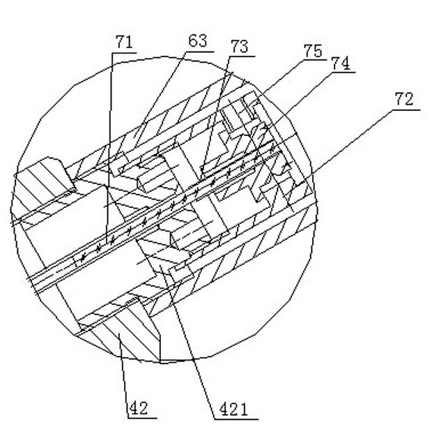
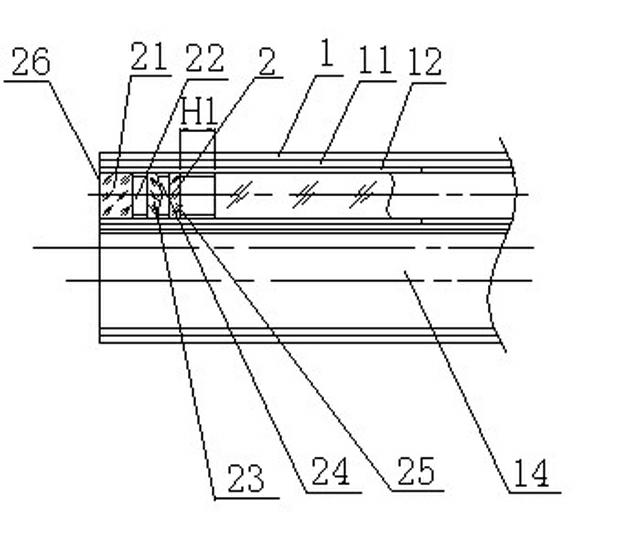
[0028] see Figure 1-Figure 8 , the present invention is mainly composed of an outer mirror tube 1, an objective lens system 2, an illuminating device 3, a main body device 4, an instrument channel device 5, an eyepiece system 6, an image relay part 7 and a water delivery device 8. Among them: the outer mirror tube 1, the lighting device 3, the instrument channel device 5, the image transfer part 7 and the water delivery device 8 are all connected to the main device 4, the objective lens system 2 is located at the front end of the outer mirror tube 1, and the eyepiece system 6 is located at the main device 4 The rear end, the lighting device 3 and the water delivery device 8 are located in the middle of the main body device 4 .

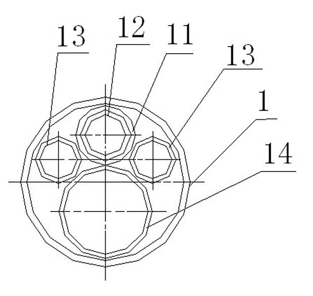
[0029] The shape of the outer mirror tube 1 of the present invention is circular, and an optical channel 11, an objective lens tube 12, a water delivery channel 13 and an instrument channel 14 are arranged in it; in the present embodiment, the working...


PUM

PropertyMeasurementUnit
Lengthaaaaaaaaaa
Outer diameteraaaaaaaaaa
The inside diameter ofaaaaaaaaaa

Abstract

The invention relates to a cervical intervertebral disc scope, which is mainly applicable to cervical vertebra and cervical intervertebral operations on human bodies. The cervical intervertebral disc scope comprises an objective system, a body device, an ocular system, an instrument channel device, a water delivery device, a lighting device and an external mirror tube, and is characterized by also comprising an image transmitting part, wherein the image transmitting part comprises an image bundle, a short tube, an image bundle rear connector, an image bundle positioning tube and an image bundle regulating screw; one end of the image bundle is matched with the objective system and the other of the image bundle is fixed with the image bundle rear connector through the short tube; the image bundle positioning tube is connected with the body device; the image bundle regulating screw is fixed on the image bundle positioning tube; and the ocular system comprises a microobjective part and a microscopicocular part, an optical duct, an objective tube, a water supply duct and the instrument channel are arranged in the external mirror tube, and the body device comprises a hollow front body and a hollow rear body. The cervical intervertebral disc scope is reasonable in structural design and small in volume, an optical system is insusceptible to breakage, and the service life of the cervical intervertebral disc scope is long.

Description

technical field [0001] The invention relates to a cervical intervertebral disc mirror, which is mainly suitable for the operation of the cervical spine and cervical intervertebral disc of the human body, and belongs to medical equipment. Background technique [0002] The human cervical spine is located between the skull and the thorax, and the cervical intervertebral discs need frequent activities under load-bearing conditions, and are susceptible to excessive minor trauma and strain. The traditional surgical method requires surgical resection of all intervertebral discs in the neck, and then implants metal grafts, artificial discs or bone tissue, which is an open major surgery. Direct opening of the spinal cavity may lead to complications such as nerve adhesions, epidural hemorrhage, nerve injury, or nerve ischemia. [0003] Chinese Patent No. 952330776 discloses a utility model patent named "cervical intervertebral disc cutting and suction treatment", which is suitable fo...

Claims


Application Information

Patent Timeline
IPC IPC(8): A61B1/00A61B17/56
Inventor 徐天松
Owner ZHEJIANG TIANSONG MEDICAL INSTR
Why Eureka
Try Eureka