

Desulfurizing and denitrifying agent for smoke gas
A denitrification agent and flue gas technology, applied in the direction of air quality improvement, dispersion particle separation, chemical instruments and methods, etc., to achieve the effect of less total investment, simple equipment and improved effect
Inactive Publication Date: 2013-02-27
NANJING UNIV OF INFORMATION SCI & TECH
View PDF4 Cites 0 Cited by
- Summary
- Abstract
- Description
- Claims
- Application Information
AI Technical Summary
Problems solved by technology
Although the desulfurizers used in these technologies are cheap, due to the complexity of the desulfurization process, the desulfurization system equipment is very large and the operation is also very complicated, and there are many limitations in actual use.
For example, it has many shortcomings such as large floor area, large amount of dosing, and high one-time investment.
At the same time, these technologies cannot achieve the purpose of denitrification at the same time, which is undoubtedly unfavorable to the transformation of combustion equipment.
Method used
View moreImage
Smart ImageViewing Examples

Examples
example
Login to View More PUM
 Abstract
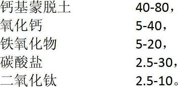
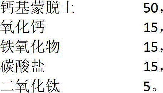
The invention discloses a smoke gas catalyst capable of simultaneously realizing desulfurization and denitrification, which aims to provide a desulfurizing and denitrifying agent for CTR-ultraviolet radiation smoke gas capable of reducing the investment and operation costs of the device and simultaneously efficiently removing the NO, NO2 and SO2 in the smoke gas. The moke gas desulfurizing and denitrifying catalyst provided by the invention may comprise the following components according to fractional ratio: 40-100% of calcium-based imvite, 0-40% of calcium oxide, 0-20% of iron oxide, 0-30% of carbonate and 0-10% of titanium dioxide, wherein the iron oxide is one or more types of ferrous oxide, iron sesquioxide and ferroferric oxide, and the carbonate is one or more types of calcium carbonate and magnesium carbonate. The desulfurizing and denitrifying agent for CTR-ultraviolet radiation smoke gas is not only suitable for the flue gas desulfurization of a new boiler but also particularly suitable for the improvement in order to construct a combustion device.
Description
technology field; [0001] The invention relates to a desulfurization and denitrification agent, in particular to designing a flue gas desulfurization and denitrification agent Background technique: [0002] The desulfurizers traditionally used in coal-fired power plants are mainly limestone and calcium hydroxide. For example, Finland's LIFAC flue gas desulfurization technology, American ABB's wet flue gas desulfurization technology and semi-dry flue gas desulfurization technology (NID system), etc. There are also NH 3 As a desulfurizing agent technology, such as the electron beam flue gas desulfurization technology researched in Japan. Although the desulfurizers used in these technologies are cheap, due to the complex desulfurization process, the desulfurization system equipment is very large and the operation is also very complicated, and there are many limitations in actual use. For example, it has many shortcomings such as large floor area, large amount of dosing, and...
Claims
Login to View More Application Information
Patent Timeline
 Patent Type & AuthorityPatents(China)
IPC IPC(8): B01D53/83B01D53/60
CPCY02A50/20
Inventor张泽锋
OwnerNANJING UNIV OF INFORMATION SCI & TECH