Single-trough floatation method adopting helical rotor, device and use
A flotation device and screw technology, used in flotation, solid separation and other directions, can solve the problem of not meeting the requirements of multi-stage flotation functions in the same tank, improve the flotation recovery rate and concentrate grade, reduce consumption and energy. consumption, and the effect of expanding the application field
- Summary
- Abstract
- Description
- Claims
- Application Information
AI Technical Summary
Problems solved by technology
Method used
Image
Examples
Embodiment 1
[0033] Example 1: A laboratory single-slot flotation device using a helical rotor
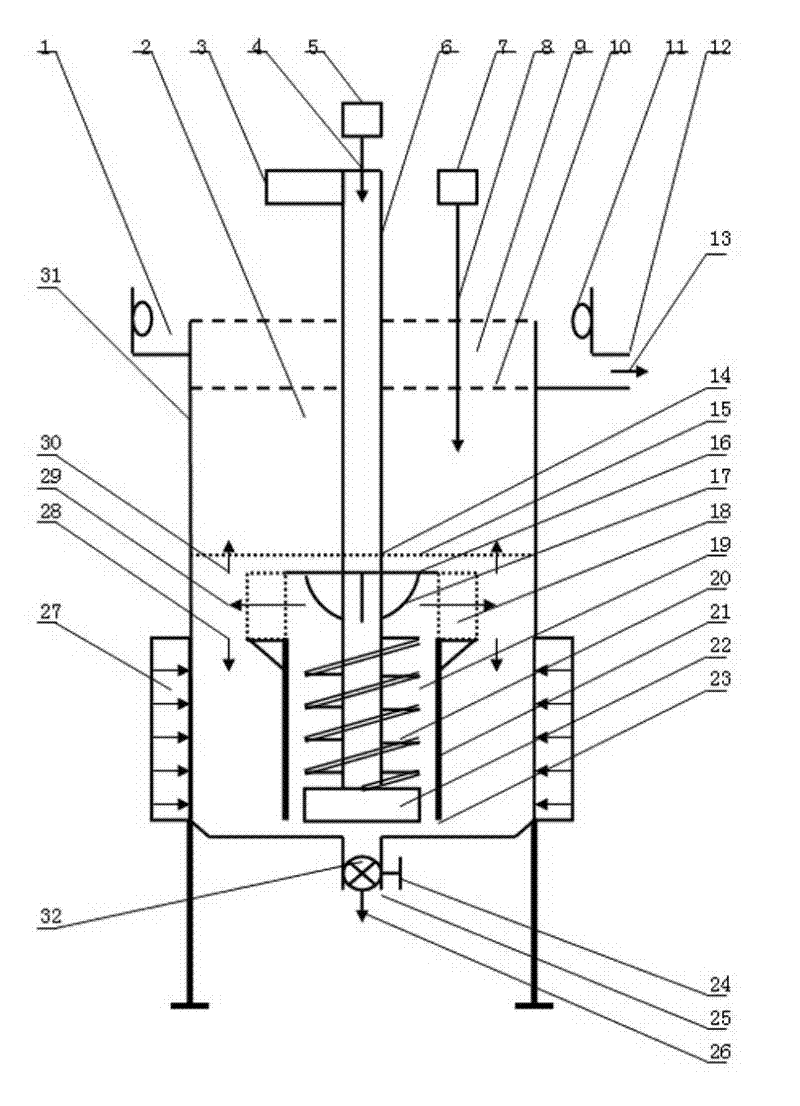
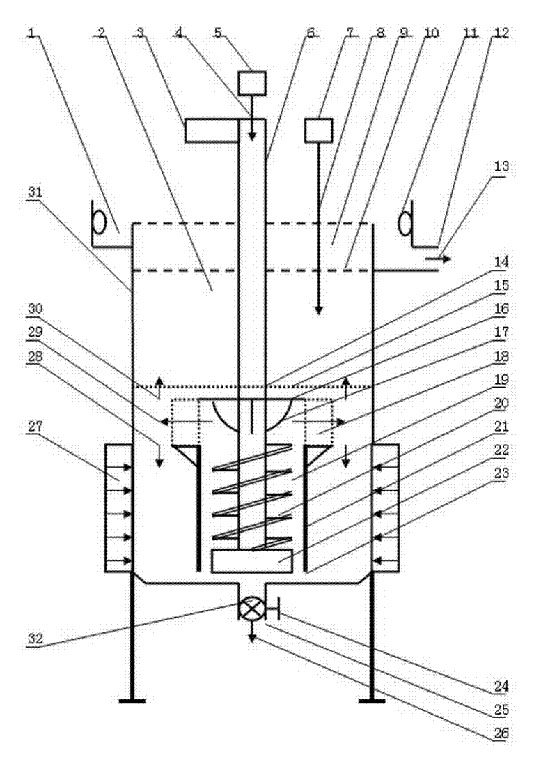
[0034] figure 1 It is a laboratory single-slot flotation device using a helical rotor. It consists of a single-cell flotation device chamber 2, a driving device 3, an air supply device 4, a dosing device 7, a floating device 19, a flow stabilization device 14, an ultrasonic device 27 and a final tailings slurry device 32. It is characterized in that: the squirrel-cage stator 18 is arranged on the top of the helical rotor chamber 21 containing the helical rotor 20; in the area contained by the squirrel-cage stator 18, there is provided at least two plates symmetrically arranged on the hollow rotor shaft 6 The dispersing impeller 17 that blade is formed; On the floating device 19 tops, be provided with at least one flow stabilizing device 14 that can be at least one deck sieve 15; Its ultrasonic device 27 is arranged on the surface of the outer wall of the cell cavity 2 of the single-cell flotat...
Embodiment 2
[0041] Embodiment 2: A kind of industrialized single-trough flotation cyanide tailings device using helical rotor
[0042] figure 1 Shown is an industrialized single tank flotation cyanide tailings plant using a helical rotor. Its technical principle is the same as that of Embodiment 1. Its working process is:
[0043] Close the bottom valve 25, and fill the cavity 2 of the single-trough flotation device with the cyanided tailings that have undergone grinding treatment according to the set slurry concentration and pH. Then add the flotation agent 8 according to the setting, and start the driving device 3 and the ultrasonic device 27 . After circulating and stirring the cyanide tailings slurry for the set time, open the air supply device 5 and add compressed air 4 according to the setting. Mineralized bubbles 30 continuously emerge from the liquid surface 10 of the ore slurry, forming a layer of mineralized bubbles in the mineralized bubble enrichment area 9 . Mineralized ...
Embodiment 3
[0047] Embodiment 3: An industrialized single-trough flotation device for lead smelting slag using a helical rotor
[0048] figure 1 Shown is an industrialized single-trough flotation device for lead smelting slag using a helical rotor. Its technical principle is the same as that of Embodiment 1. Its working process is:
[0049] Close the bottom valve 25, and fill the cavity 2 of the single-trough flotation device with the ground lead smelting slag according to the set slurry concentration and pH. Then add the flotation agent 8 according to the setting, and start the driving device 3 and the ultrasonic device 27 . After the lead smelting slag slurry is circulated and stirred until the set time, the air supply device 5 is opened, and the compressed air 4 is added according to the setting. Mineralized bubbles 30 continuously emerge from the liquid surface 10 of the ore slurry, forming a layer of mineralized bubbles in the mineralized bubble enrichment area 9 . Mineralized b...
PUM
| Property | Measurement | Unit |
|---|---|---|
| Aperture | aaaaa | aaaaa |
Abstract
Description
Claims
Application Information
 - R&D Engineer
- R&D Manager
- IP Professional
- Industry Leading Data Capabilities
- Powerful AI technology
- Patent DNA Extraction
Browse by: Latest US Patents, China's latest patents, Technical Efficacy Thesaurus, Application Domain, Technology Topic, Popular Technical Reports.
© 2024 PatSnap. All rights reserved.Legal|Privacy policy|Modern Slavery Act Transparency Statement|Sitemap|About US| Contact US: help@patsnap.com


