Method for processing cycloid-involute spiral bevel gears and solid cutter

A technology of a spiral bevel gear and a processing method, which is applied to components with teeth, metal processing equipment, gear teeth manufacturing tools, etc., can solve the problems of difficult processing, complex structure of the cutter head and spindle, and poor rigidity of the double cutter head.

Inactive Publication Date: 2011-09-14
CHANGSHA HALIANG KAISHUAI PRECISION MASCH CO LTD
View PDF4 Cites 12 Cited by
  • Summary
  • Abstract
  • Description
  • Claims
  • Application Information

AI Technical Summary

Problems solved by technology

[0011] Obviously, the rigidity of this two-body cutter head is poor and the manufacturing is complicated

Method used


Image

  • Method for processing cycloid-involute spiral bevel gears and solid cutter
  • Method for processing cycloid-involute spiral bevel gears and solid cutter
  • Method for processing cycloid-involute spiral bevel gears and solid cutter

Examples


Embodiment approach

[0076] As a preferred embodiment, the actual parameters of the cycloid-involute spiral bevel gear are:

[0077]

[0078]

[0079] The processing parameters of the large wheel are determined according to the helix angle of the midpoint of the convex surface of the large wheel is ψ:

[0080] N C = N sin Γ = 54.7448

[0081]

[0082] S = A 2 + r C 2 - 2 A r C sin ( ψ - v ) = 316.97 mm

[0083]

[0084] q=ψ+η=61.3152°

[0085] The helix angle of the concave surface of the big wheel is:

[0086] R = ...


PUM


Abstract

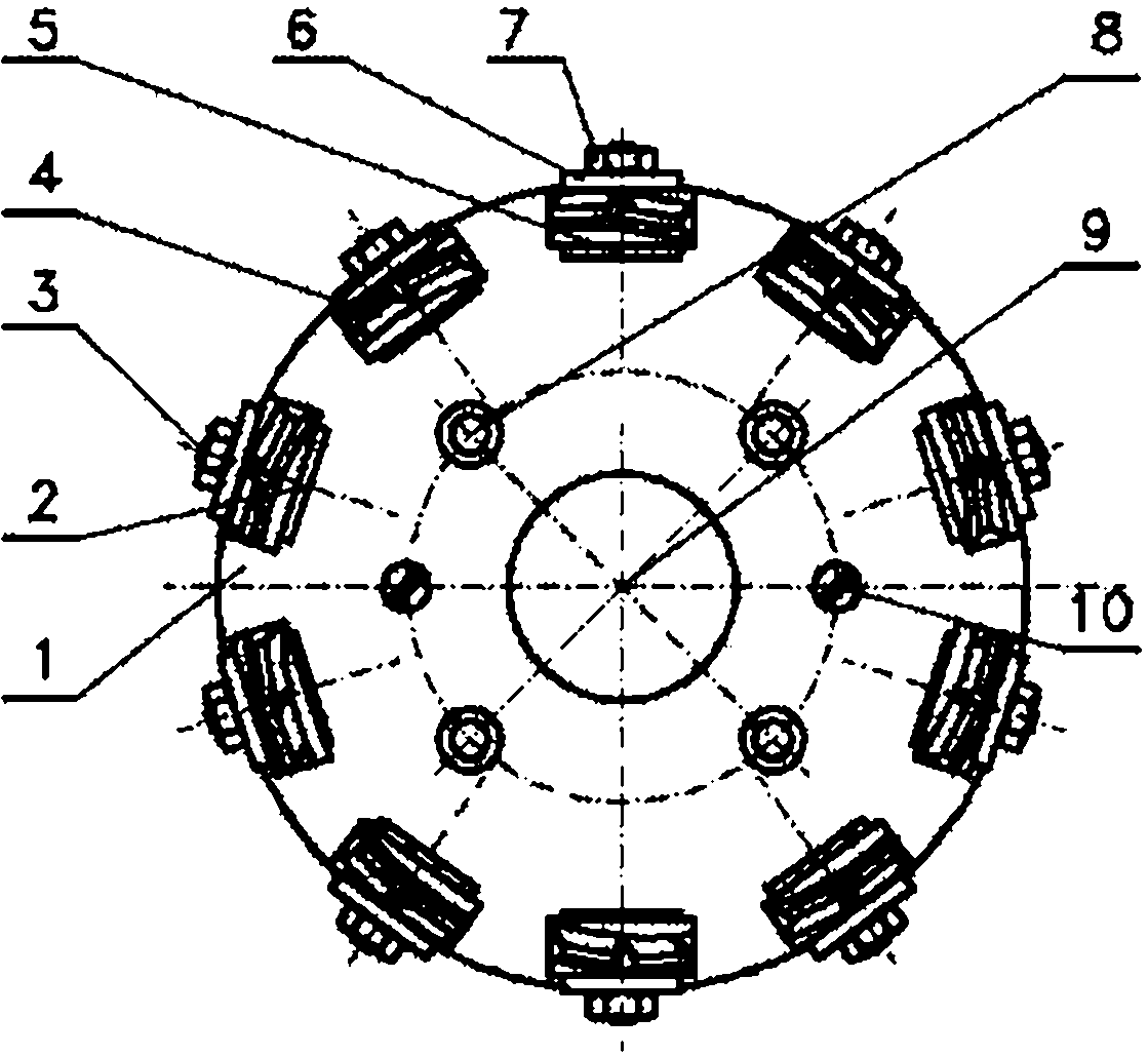
The invention discloses a method for processing cycloid-involute spiral bevel gears on general digital control gear milling machines and a corresponding solid cutter, and belongs to the field of spiral bevel gear processing. According to the method, a large wheel can be processed by a double-sided method and a small wheel is processed by the double-sided method or a single-sided method. After a gear is subjected to heat treatment, the gear is shaved or ground. The cutter for processing the gear is integral; an installation structure of the cutter body on a machine tool is the same as a cutter installation structure used by the general digital control gear milling machines, and a soft cutting cutter head and a hard cutting cutter head used on the cutter and the assembly structure and method thereof are consistent with those used for the cycloid-involute spiral bevel gears. The cutter adopted in the method is simple in structure and easy to manufacture, and can perform processing on the general digital control machine tools without accessories or special designs, so the cycloid-involute spiral bevel gears can be easily promoted in industrial circles.

Description

technical field [0001] The invention relates to the field of spiral bevel gear processing, specifically a method for processing cycloid-involute spiral bevel gears and an integral cutterhead for processing such gears, which can be processed on a general-purpose milling machine. Spiral bevel gear. Background technique [0002] For the large-scale spiral bevel gears used in mining, metallurgy, building materials, energy and other industries, most foreign countries use the cycloid-quasi-involute system (Cycle-Palloid System) invented by the German Klingelnberg company in 1964. This tooth system adopts The double-body cutter head is processed by continuous hobbing on a special machine tool, and the gear is scraped with a cutter tooth equipped with a CBN cutter head after heat treatment. The advantage of this tooth system is that the adjustment of the contact area is simple and convenient, and no special software is required to calculate the gear cutting. It is very suitable for...

Claims


Application Information

Patent Timeline
IPC IPC(8): B23F5/20B23F21/16
Inventor 曾亦愚王志永曾韬
Owner CHANGSHA HALIANG KAISHUAI PRECISION MASCH CO LTD
Why Eureka
Try Eureka