Eureka AIR delivers breakthrough ideas for toughest innovation challenges, trusted by R&D personnel around the world.

Device for converting lumpy high-low water head potential energy difference into electric energy

A technology of undulating waves and potential energy, applied in safety devices, ocean energy power generation, mechanical equipment, etc., can solve problems such as lack of 24-hour uninterrupted power generation, safe operation of power grid and negative impact of power structure configuration, and climate problems

Inactive Publication Date: 2011-09-14
王谢林 +1
View PDF5 Cites 5 Cited by
  • Summary
  • Abstract
  • Description
  • Claims
  • Application Information

AI Technical Summary

Problems solved by technology

[0003] 1. Wind power generation must rely on thermal power peak regulation: due to the fatal weakness of wind power, which is random and intermittent, there is currently no way to arrange and control its output like other conventional energy sources; up to now, the average annual power generation time of a single fan in my country It is less than 1500 hours. Therefore, if wind power is developed in a large-scale and centralized manner, it will have a certain negative impact on the safe operation and power structure configuration of the local power grid and even larger regional power grids; experts estimate that when the proportion of wind power in the total electricity exceeds 5-10%. , it will pose a threat to the security and stability of the power grid, and it will easily lead to the collapse of the power grid; it is reported that the National Development and Reform Commission has stopped the approval of some wind power projects
[0004] 2. Solar power generation is divided into two types: photovoltaic power generation and photothermal power generation. Of course, it does not have the conditions for 24-hour non-intermittent power generation: photovoltaic power generation is currently the mainstream, but its energy conversion rate is low, generally only about 13%. The improved expectations have limited prospects; although the energy conversion rate of the emerging solar thermal power generation can approach the maximum conversion rate of about 40%, its cost is not only more than double that of photovoltaic power, but also limited to the annual sunshine radiation Areas above 2000 kWh / m2, and the land slope does not exceed 3%, need to allocate the same amount of water consumption as thermal power, many conditions restrict its development
[0005] 3. Other renewable energy sources such as reservoir power generation, biomass energy, geothermal energy, seawater temperature difference energy, vegetable oil, fuel cells, biological batteries, hydrogen combustion, etc., which compete with people for food, are also due to their small feasible scale, or due to the current The craft is difficult to complete without climate change
[0007] All currently feasible renewable energy sources are unable to compete with thermal power in actual use: first, it is impossible to achieve uninterrupted normal power supply; second, there is a huge gap in price; third, it cannot meet the current scale of electricity consumption

Method used


Image

  • Device for converting lumpy high-low water head potential energy difference into electric energy
  • Device for converting lumpy high-low water head potential energy difference into electric energy
  • Device for converting lumpy high-low water head potential energy difference into electric energy

Examples


Embodiment Construction

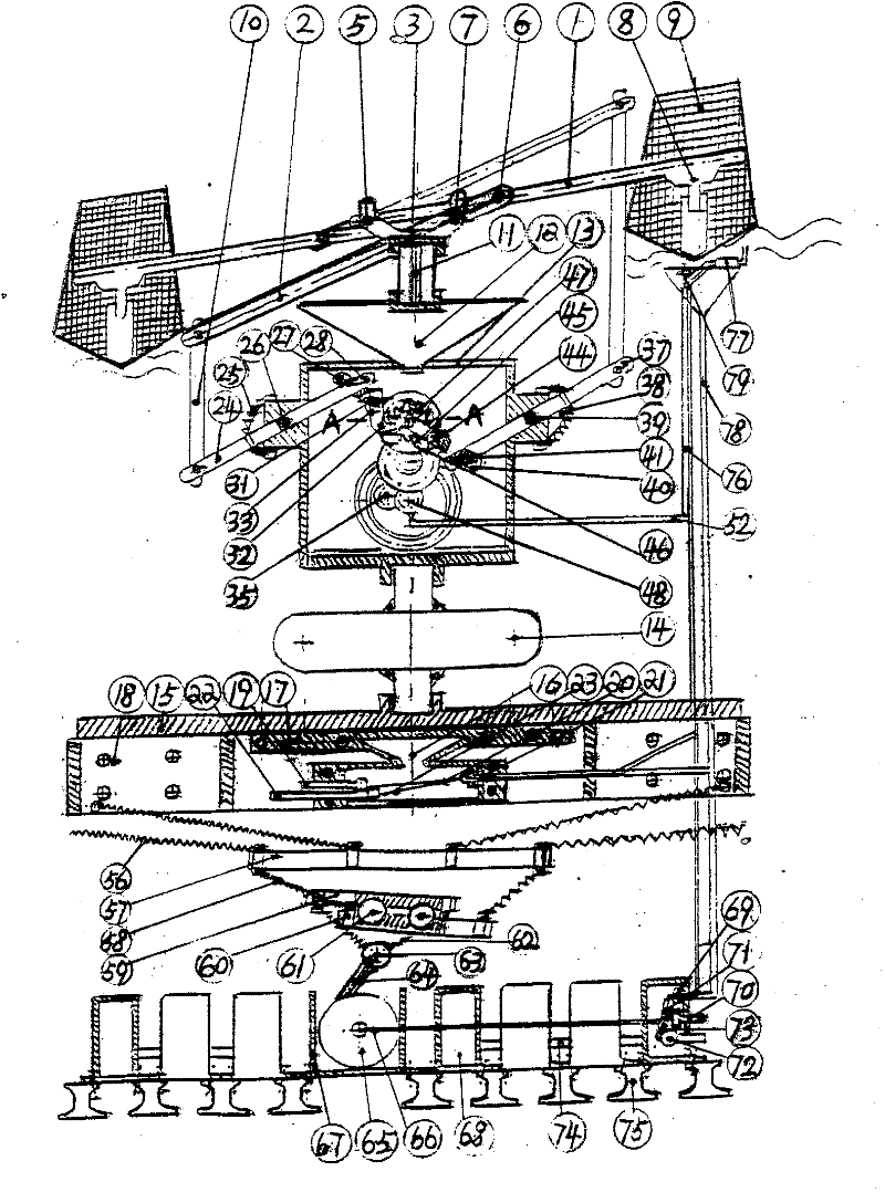
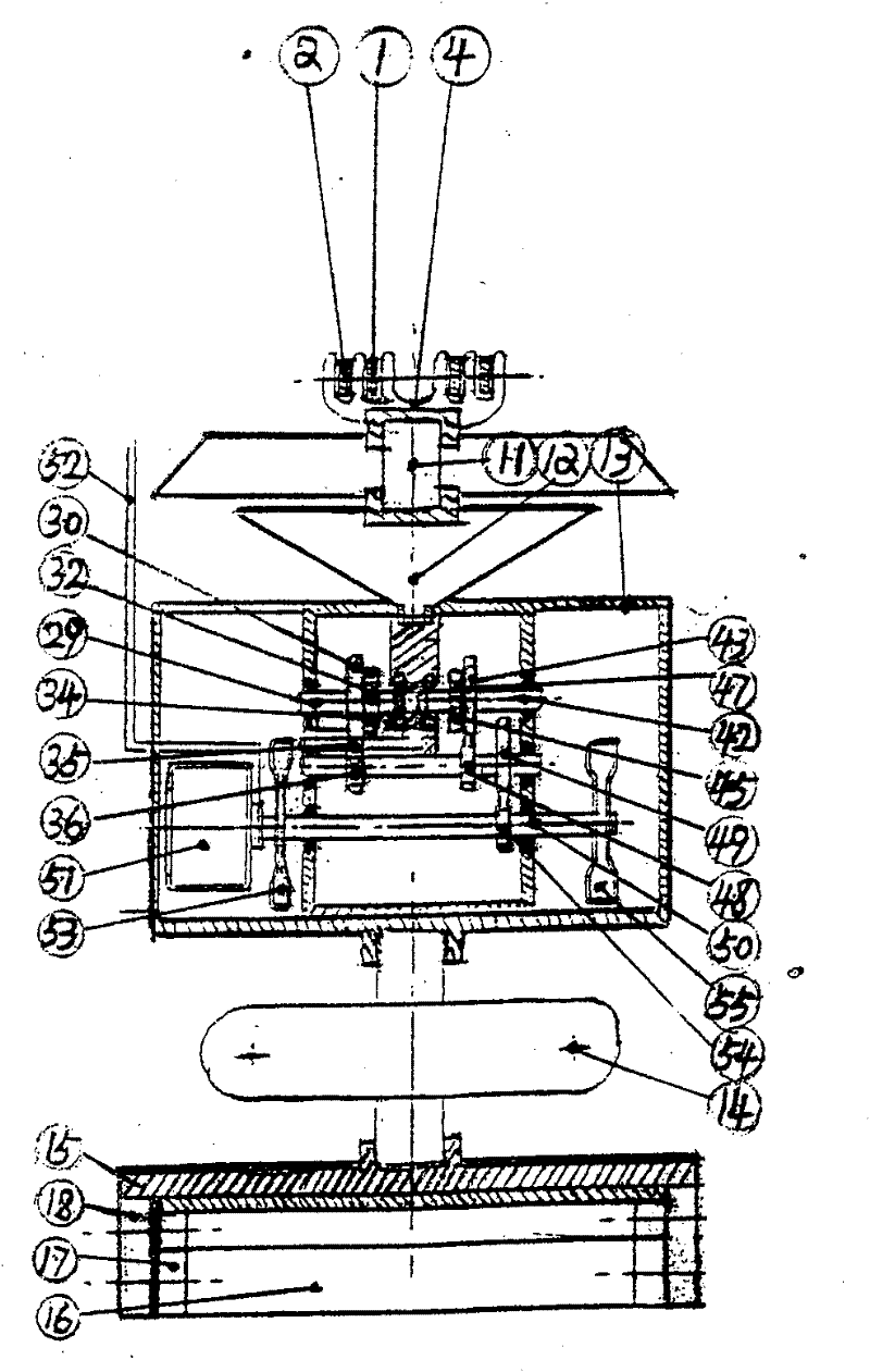
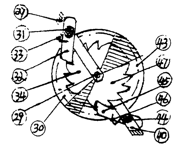
[0032] Work buoyancy tank The structure of (9) has a large bottom and a small top, with sharp angles at both ends, the purpose is to extract the wave potential energy with the largest contact area with the wave, and at the same time slow down the reactive swing of the transverse wave. Floating tank The upper end passes through the conical frame with a large bottom and a small top to make the potential energy of the wave move to pontoon rocker (1) On the stress point of the end, so that when a wave rises, it will drive the jacking Work buoyancy tank (9) and Floating tank installed in Ballast tank (8) rise synchronously, and also drive pontoon rocker (1) The force end rises, Rocker By virtue of its end mounted on the Fork head and bearing seat of left column (4) or Right column yoke and bearing seat (3) of Rocker beam and fork head fulcrum shaft and bearing (5) As the fulcrum rises or falls; Rocker Ascent through Shafts and bearings shared by rocker beams a...


PUM


Abstract

The invention discloses a high-sea never-ending wave potential energy power generation device which is the only one device disclosing three advantages (normal power supplying, large scale and low power cost) by combining thermal power in pollution-free clean energies. According to the invention, the device comprises a floating tank, a water tank, a moving rod, a watering gravity center positioning connecting groove, a conical floating drum, an underwater balance wing flow plate, a guide wheel of a guide plate, a spring, a weight frame, a ratchet wheel constant speed flywheel and the like, wherein the floating tank and the water tank are utilized to do work twice for the upsurge and calmness of the same wave; ceaseless power generation can be carried out according the minimum wave heaving value by utilizing work doing based on stormy waves and also utilizing the moving rod with amplified work-doing amplitude; the watering gravity center positioning connecting groove and the conical floating drum are used for keeping the best work-doing semi-submersion depth and providing gravity center positioning; the connecting groove can be spliced into the required integral scale; the underwater balance wing flow plate of a counteracting force platform is provided by utilizing an underwater stable water body and a water level wave heaving difference; the guide wheel of the guide plate and the spring can automatically correct the inclination of a water-borne device; the integral device is delivered to an immersion point and is immersed after being assembled on land, and the weight frame can position and provide controllable pulling for a power generation device; and the ratchet gear constant flywheel can convert the wave potential energy into electric power energy.

Description

Technical field: [0001] The kinetic energy of the mechanical power generation device of the present invention is converted from the potential energy difference between the high and low water head of the undulating waves in the far sea beyond the maximum tidal line of the sea surface, which belongs to the energy source that utilizes natural energy, does not discharge waste, and is eternally clean; Potential energy is generated by the superposition of various natural energies on the water surface, so it is more in line with the actual needs of human beings than any single natural energy. It has inexhaustible and regenerated energy at any time; more precious is: the undulation of waves The potential energy has the characteristics of constant, long-lasting, never-ending, and has a huge scale that can be developed almost infinitely; wave power generation has neither the pollution nor carbon emissions of thermal power, but also has all the favorable elements of thermal power use, which...

Claims


Application Information

Patent Timeline
IPC IPC(8): F03B13/14F03B15/00
CPCY02E10/38Y02E10/30
Inventor 王谢林王啸风
Owner 王谢林
Why Eureka
Eureka Blog
Learn More