Vehicle-mounted unit of 5.8 GHz electronic toll collection system
An electronic non-stop, on-board unit technology, applied in instruments, ticketing equipment, etc., can solve problems such as vehicle congestion at toll stations, loss of fares, and on-site disputes, achieving high stability and reliability, convenient use and maintenance, and investment. low cost effect
- Summary
- Abstract
- Description
- Claims
- Application Information
AI Technical Summary
Problems solved by technology
Method used
Image
Examples
Embodiment 1
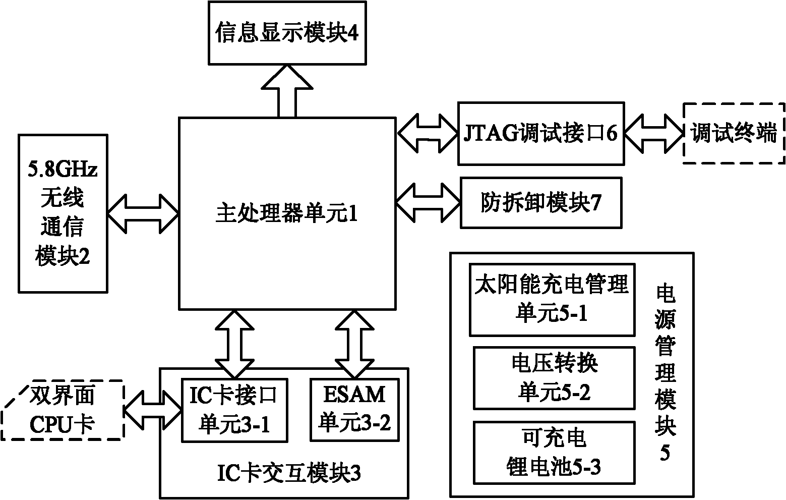
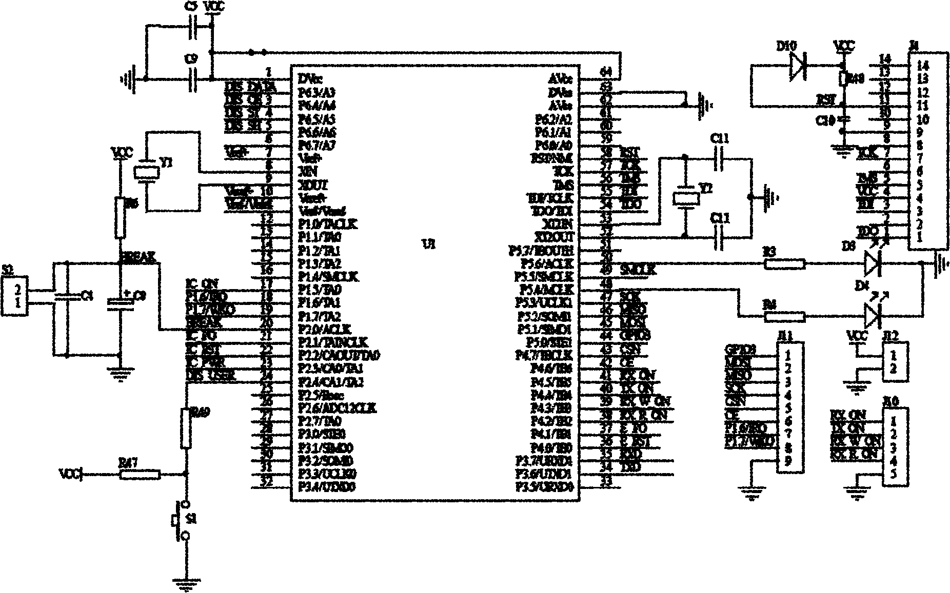
[0053] The above-mentioned main processor unit 1, JTAG debugging interface 6 and anti-disassembly module 7 see figure 2 .
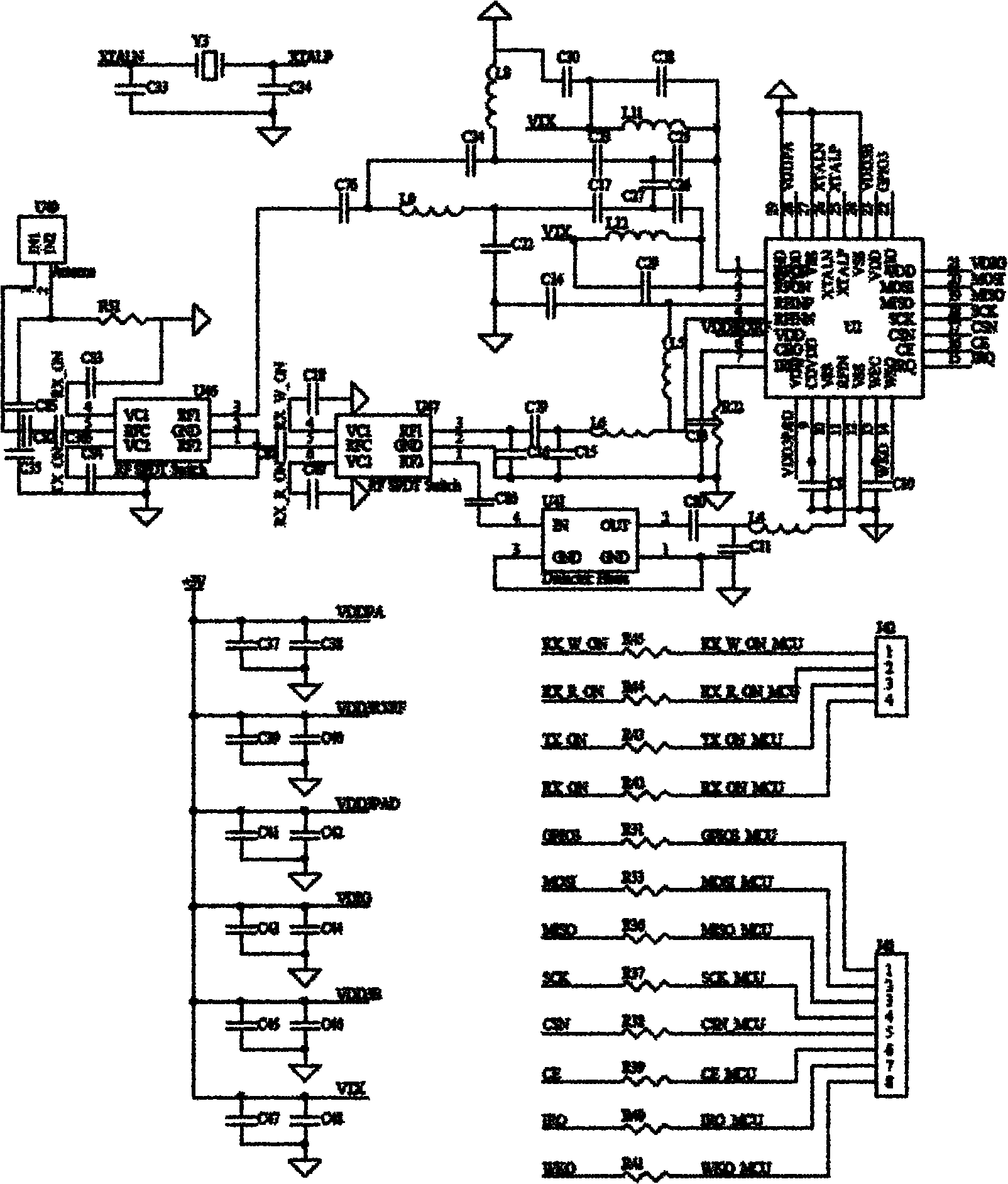
[0054] The microprocessor chip U1 in the main processor unit 1 selects TI's high-performance, low-power consumption MSP43016-bit high-end microprocessor MSP430F149. It adopts the reduced instruction set RISC structure, has rich addressing modes, concise kernel instructions and a large number of simulation instructions, a large number of registers and on-chip data memory can participate in various operations, and efficient look-up table processing instructions; Driven by an 8MHz crystal, it can achieve a 125ns instruction cycle, and has abundant peripherals, interrupts, and I / O resources; it has 5 low-power modes, and in the low-power mode, the minimum power consumption of the system can be reduced to uA level , and all interrupts can wake up the system from low power consumption mode, the wake-up time is only 6us; it has a JTAG interface compatible with...
Embodiment 2
[0063] According to the selected chip and connection mode of embodiment 1, the workflow of microprocessor chip U1 processing 5.8GHz wireless data communication in main processor unit 1 is as follows Figure 7 As shown, it includes:
[0064] Step 1 After entering the IRQ interrupt handler, disable the IRQ interrupt enable.
[0065] Step 2 reads the value of each interrupt register, and judges the interrupt flag bit.
[0066] (1) If the wake-up interrupt flag is valid, clear the wake-up interrupt flag and go to step 3.
[0067] (2) If the sending completion interrupt flag is valid, clear the sending completion interrupt flag and go to step 3.
[0068] (3) If the reception completion interrupt flag is valid, then clear the reception completion interrupt flag, read the data in the RX_FIFO register in the radio frequency transceiver chip U2, and proceed to step 4.
[0069] (4) If the above-mentioned three interrupt flags are all invalid, then receive error, clear the receive err...
Embodiment 3
[0075] According to the selected chip and connection mode of embodiment 1, the workflow of microprocessor chip U1 realizing vehicle charging in main processor unit 1 is as follows Figure 8 As shown, it includes:
[0076] Step 1 clears the transaction completion flag, and proceeds to step 2.
[0077] step 2
[0078] (1) If the status of the CPU card is normal, go to step 3.
[0079] (2) If the status of the CPU card is abnormal, a message will be displayed to prompt the user to insert a valid CPU card, and return to step 2.
[0080] step 3
[0081] (1) Receive the RSU command, if the received RSU command has not timed out, go to step 4.
[0082] (2) If the received command times out, go to step 10.
[0083] Step 4 Interpret the received RSU command
[0084] (1) If it is a command to read system / vehicle / transaction record information, go to step 5.
[0085] (2) If it is to receive the transaction record command, then receive the transaction record data and go to step 7. ...
PUM
 Abstract
Description
Claims
Application Information
 - R&D
- Intellectual Property
- Life Sciences
- Materials
- Tech Scout
- Unparalleled Data Quality
- Higher Quality Content
- 60% Fewer Hallucinations
Browse by: Latest US Patents, China's latest patents, Technical Efficacy Thesaurus, Application Domain, Technology Topic, Popular Technical Reports.
© 2025 PatSnap. All rights reserved.Legal|Privacy policy|Modern Slavery Act Transparency Statement|Sitemap|About US| Contact US: help@patsnap.com


