Semiconductor structure and formation method, pmos transistor and formation method
A semiconductor and silicon-on-insulator technology, applied in the fields of semiconductor devices, semiconductor/solid-state device manufacturing, electrical components, etc., can solve the problems of poor substrate, complex process flow, influence, etc., and achieve the effect of increasing volume and enhancing compressive stress
- Summary
- Abstract
- Description
- Claims
- Application Information
AI Technical Summary
Problems solved by technology
Method used
Image
Examples
Embodiment 1
[0040] Figure 2 to Figure 5 It is a schematic diagram of an embodiment of forming a semiconductor structure in the present invention.
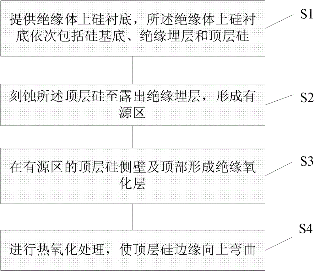
[0041] First, if figure 2 As shown, a silicon-on-insulator substrate is provided, and the silicon-on-insulator substrate includes a silicon base 11 , an insulating buried layer 12 and a top layer of silicon 13 in sequence.
[0042] Optionally, the material of the buried insulating layer 12 is silicon oxide.
[0043] Such as image 3 As shown, the top silicon layer 13 is etched to expose the buried insulating layer 12 , and an active region is formed on the buried insulating layer 12 . The specific process is as follows: first coat a layer of photoresist layer (not shown) on the top layer of silicon 103, and define the pattern of the active region after the photolithography process; then use the photoresist layer as a mask, The top layer silicon 13 is etched in the active area pattern to expose the insulating buried layer 12 , and the act...
Embodiment 2
[0057] refer to Figure 7 to Figure 8 What is shown is a schematic diagram of a formation process of a PMOS transistor according to the present invention.
[0058] like Figure 7 As shown, a silicon-on-insulator substrate is provided, wherein the top-layer silicon 13a of the active region in the silicon-on-insulator substrate is bent upwards, and the specific method of forming the top-layer silicon 13a of the active region bent upwards is the same as that described in Embodiment 1. , which will not be repeated here.
[0059] continue to refer Figure 7 A gate dielectric layer 15 and a polysilicon gate 16 are sequentially formed on the top layer of silicon 13a in the active region; lightly doped regions 14 are formed in the top layer of silicon 13a in the active region on both sides of the polysilicon gate 16 . The specific formation process is as follows: a first photoresist layer (not shown) is coated on the top layer of silicon 13a in the active region; after exposure and...
Embodiment 3
[0065] Figure 9 to Figure 18 It is a schematic diagram of an embodiment process of forming a CMOS device structure of the present invention.
[0066] First, if Figure 9 As shown, a silicon-on-insulator substrate is provided, wherein the silicon-on-insulator substrate includes a silicon base 11 , an insulating buried layer 12 and a top layer of silicon 13 in sequence. Optionally, the material of the buried insulating layer 12 is silicon oxide or silicon nitride.
[0067] like Figure 10 As shown, the top layer silicon 13 is etched to expose the insulating buried layer 12, and the active region top layer silicon 13a of the PMOS device region and the active region top layer silicon 13b of the NMOS device region are formed on the insulating buried layer 12. The specific process is as follows: first coat a layer of photoresist layer (not shown) on the top layer of silicon 103, and after the photolithography process, respectively define the active area patterns of the PMOS devi...
PUM
 Abstract
Description
Claims
Application Information
 - R&D
- Intellectual Property
- Life Sciences
- Materials
- Tech Scout
- Unparalleled Data Quality
- Higher Quality Content
- 60% Fewer Hallucinations
Browse by: Latest US Patents, China's latest patents, Technical Efficacy Thesaurus, Application Domain, Technology Topic, Popular Technical Reports.
© 2025 PatSnap. All rights reserved.Legal|Privacy policy|Modern Slavery Act Transparency Statement|Sitemap|About US| Contact US: help@patsnap.com


