
Nanometer carbon fiber vacuum superconducting heat pipe and manufacturing method thereof

A nano-carbon fiber, super heat-conducting tube technology, applied in tubular elements, heat exchange equipment, lighting and heating equipment, etc., can solve the problems of decreased heat transfer efficiency, easy corrosion of tube walls, easy fatigue of heat pipes, etc., and achieves fast heat transfer speed. , good temperature uniformity, the effect of a wide range of applicable temperatures

Active Publication Date: 2014-05-07
XIAMEN GREENER OPTOELECTRONICS
View PDF8 Cites 0 Cited by
  • Summary
  • Abstract
  • Description
  • Claims
  • Application Information

AI Technical Summary

Problems solved by technology

Since the main components of the heat transfer medium are liquid and additives, the heat transfer medium is limited by its own properties, and the shell is limited by the temperature and cycle phase change speed, so the heat conduction efficiency of conventional heat pipes is only slightly greater than 60%, and the heat loss is high. The heat pipe is very easy to fatigue, the pipe wall is easy to corrode, and the service life is not long
After one or two years of use of most heat pipes, the heat transfer efficiency will drop significantly

Method used


Image

  • Nanometer carbon fiber vacuum superconducting heat pipe and manufacturing method thereof
  • Nanometer carbon fiber vacuum superconducting heat pipe and manufacturing method thereof

Examples


Embodiment Construction

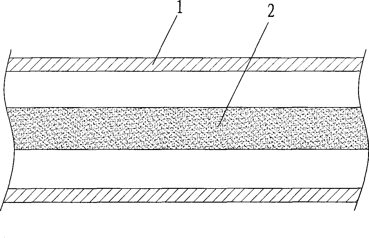
[0042] Such as figure 1 As shown, a carbon nanofiber vacuum superconducting heat pipe disclosed by the present invention includes a vacuum tube 1 and a superconducting medium 2 made of carbon nanofibers.

[0043] Among them, the vacuum tube 1 is formed by sealing the tube shell and the end cap, and can be made of copper, carbon steel, stainless steel and other metals or non-metallic tubular or plate materials such as glass and ceramics; the superconducting medium 2 is a mixture of nano-carbon fibers. The superconducting medium 2 is injected into the vacuum tube 1, and after sealing and forming, a high-efficiency heat pipe is formed.

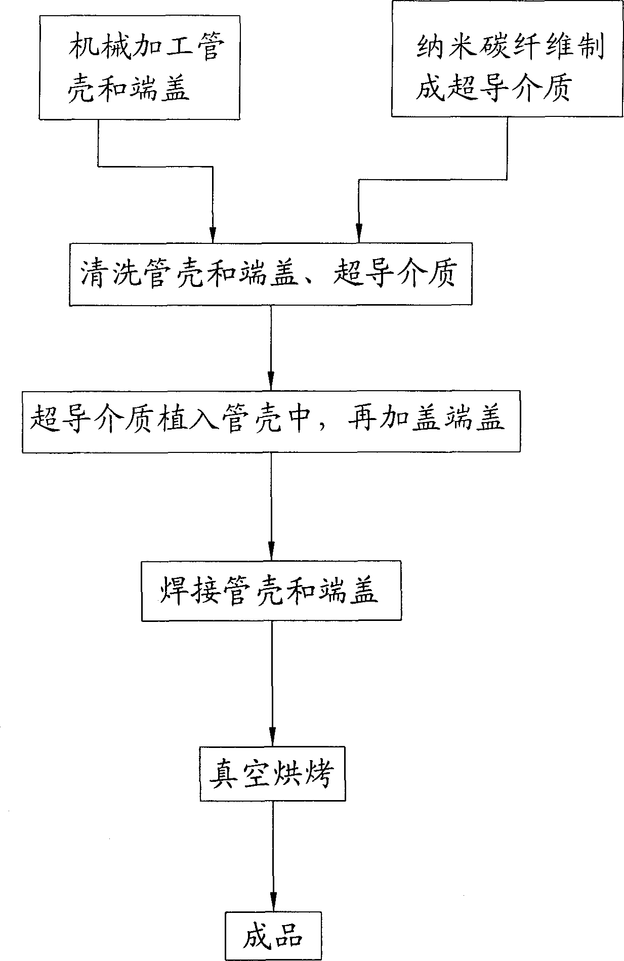
[0044] The specific processing of the superconducting heat pipe, such as figure 2 As shown, the shell and end cap of the vacuum tube are made by machining first. The selection of the shell material should pay attention to the characteristics of thermal conductivity, vacuum maintenance, pressure resistance, fluid compatibility (corrosion, chemic...


PUM

PropertyMeasurementUnit
diameteraaaaaaaaaa
diameteraaaaaaaaaa
thermal conductivityaaaaaaaaaa

Abstract

The invention discloses a nanometer carbon fiber vacuum superconducting heat pipe which comprises a superconducting medium prepared from a vacuum pipe and nanometer carbon fibers, wherein the vacuum pipe is formed by sealing a pipe shell and an end cover; and the superconducting medium is implanted in the sealed vacuum pipe. The manufacturing method comprises the following steps: firstly machining the pipe shell and end cover of the vacuum pipe, and manufacturing the superconducting medium by adopting the nanometer carbon fibers; then cleaning, scrubbing and dedusting the pipe shell, the end cover and the superconducting medium; then implanting the superconducting medium into the pipe shell, and capping the end cover; then welding the pipe shell and the end cover, checking whether the vacuum pipe leaks air, removing the air in the vacuum pipe, and sealing the vacuum pipe; and finally carrying out vacuum roasting, and carrying out dehydration and deoxidation treatment on the capillary surface for a heat pipe assembly at the high temperature of 200+ / -10 DEG C under the vacuum environment, thus the finished product is obtained. According to the invention, because the heat transfer medium is composed of the nanometer carbon fibers, under the stimulation of the external temperature difference, heat is transferred by virtue of the high-frequency vibration of macroparticles, and the heat pipe has the advantages of no phase change, extremely small heat resistance and long service life.

Description

technical field [0001] The invention relates to the technical field of a high-efficiency heat pipe, in particular to a nano-carbon fiber vacuum superconducting heat pipe and a processing method thereof, which can be widely used in various heat transfer and related products, such as solar energy (water heaters, heating equipment, etc.), petroleum, Chemical industry, metallurgy, electric power, electronics, building materials, renewable energy, permafrost prevention, road snow melting, etc. Background technique [0002] A conventional heat pipe is composed of a tube shell, a liquid-absorbing core and an end cover. After the negative pressure drawn from the tube shell is filled with an appropriate amount of working liquid, the capillary porous material of the liquid-absorbing core close to the inner wall of the tube is filled with liquid, and then To be sealed. One end of the shell is the evaporating section (heating section), the other end is the condensing section (cooling s...

Claims


Application Information

Patent Timeline
Patent Type & Authority Patents(China)
IPC IPC(8): F28F1/00
Inventor 叶永典廖良斌
Owner XIAMEN GREENER OPTOELECTRONICS
Learn More