Magnetic-field measurement device and manufacturing method thereof as well as magnetic-field measurement method

A magnetic field measurement and optical fiber technology, which is applied in the field of magnetic field measurement devices, can solve the problems of time-consuming, time-consuming, and the confocal microscope system is not easy to transplant, and achieves the effect of saving time and manpower and reducing costs.

Inactive Publication Date: 2011-09-21
UNIV OF SCI & TECH OF CHINA
View PDF5 Cites 41 Cited by
  • Summary
  • Abstract
  • Description
  • Claims
  • Application Information

AI Technical Summary

Problems solved by technology

[0009] 1) The confocal microscopy system requires the best microscopic imaging system and nanoscale scanning system, so it will inevitably lead to high costs;
[0010] 2) It takes a lot of time and manpower to find and locate a single NV color center, so in the process of using a single NV color center to measure the magnetic field, it will inevitably consume a lot of time and manpower to find and locate a single NV color center;
[0011] 3) Since the focus of the confocal microscope system will drift due to various external factors such as temperature and interference, the positioning of a single NV color center will be unstable, thereby affecting the accuracy of ma...

Method used


Image

  • Magnetic-field measurement device and manufacturing method thereof as well as magnetic-field measurement method
  • Magnetic-field measurement device and manufacturing method thereof as well as magnetic-field measurement method
  • Magnetic-field measurement device and manufacturing method thereof as well as magnetic-field measurement method

Examples


Embodiment 1

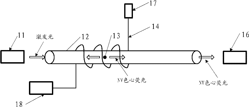
[0072] The structure diagram of the magnetic field measuring device disclosed in this embodiment is as follows: image 3 with Figure 4 As shown, the device includes:

[0073] A combined optical fiber 12 formed by connecting two optical fibers;

[0074] The single-crystal diamond particles 13 with a single NV color center encapsulated between the end faces of the two optical fibers, the single-crystal diamond particles 13 are also in the combined optical fiber 12, and nano-scale or micron-scale is preferably used in this embodiment. Single crystal diamond particles, that is, single crystal diamond particles with a diameter of several nanometers to hundreds of nanometers;

[0075] a microwave transmission line arranged on the outer wall of the combined optical fiber 12;

[0076] It should be noted that, if figure 1 with figure 2 As shown, the microwave transmission line is mainly used to transmit microwaves to load the microwaves onto the single NV color center in the com...

Embodiment 2

[0090] Corresponding to the previous embodiment, this embodiment discloses the manufacturing method of the magnetic field measuring device described in the previous embodiment, the flow chart of the method is as follows Figure 5 shown, including the following steps:

[0091] Step S11: fixing two optical fibers, the end faces of the two optical fibers are opposite and located on the same straight line, wherein one optical fiber is connected to a laser to transmit excitation light, and the other optical fiber is connected to a spectrometer;

[0092] Specifically, in the embodiment of the present invention, an optical fiber holder may be used to fix the two optical fibers, especially the opposite end faces of the two optical fibers, so as to ensure the stability of the optical fibers during the packaging process.

[0093] Such as Image 6 As shown, it is a schematic diagram of the placement of two optical fibers. In this embodiment, only the a end face of 1# optical fiber is co...

Embodiment 3

[0133] The flow chart of the magnetic field measurement method disclosed in this embodiment is as follows Figure 8 As shown, the method uses the magnetic field measuring device described in Embodiment 1 to measure the magnetic field strength, and the method includes the following steps:

[0134] Step S21: Input excitation light at one end of the combined optical fiber to excite a single NV color center to generate fluorescence, and connect the other end to a spectrometer so as to measure the fluorescence intensity of the single NV color center in the combined optical fiber at any time, and transmit it in the microwave transmission line Input microwaves of a certain frequency;

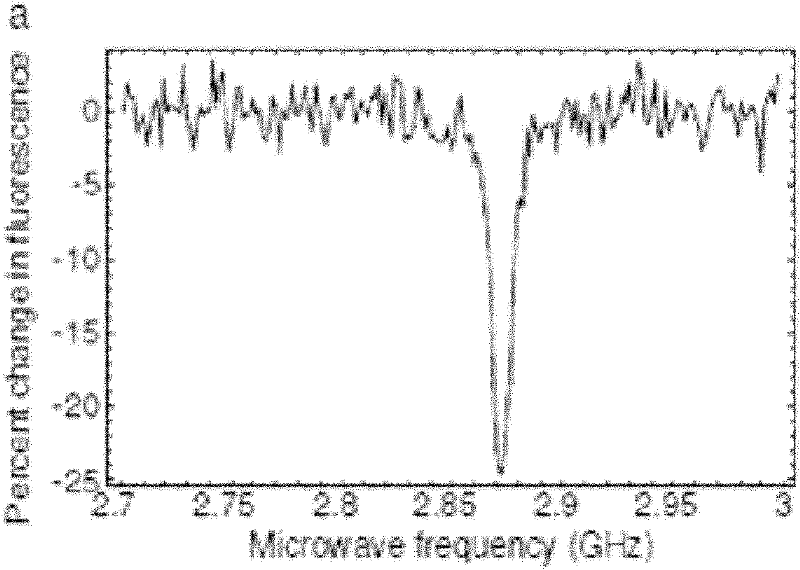
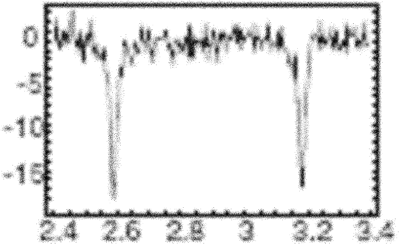
[0135] Step S22: using a standard magnetic field to calibrate the single NV color center in the combined optical fiber to obtain the microwave frequency difference corresponding to the magnetic field per unit intensity;

[0136] Step S23: Place the combined optical fiber that has been calibrated with ...


PUM


Abstract

The embodiment of the invention discloses a magnetic-field measurement device and a manufacturing method thereof as well as a magnetic-field measurement method. The magnetic-field measurement device comprises a combined optical fiber, monocrystal diamond particles, a microwave transmission line, a microwave generator, a laser device and a spectrometer, wherein the combined optical fiber is prepared by connecting two optical fibers; the monocrystal diamond particles are packaged between the end faces of the two optical fibers and provided with single NV colour centers; the microwave transmission line is arranged at the external wall of the combined optical fiber; the microwave generator is connected with the microwave transmission line; the laser device is connected with one end of the combined optical fiber; and the spectrometer is connected with the other end of the combined optical fiber; and exciting lights are input from one end of the combined optical fiber, and fluorescent lights of single NV colour centers are received from the other end of the combined optical fiber. In the invention, through carrying out measurement on magnetic fields by using the single NV colour centerspackaged in the optical fiber, the application of a confocal microscope system is avoided, the cost for finding the single NV colour centers is reduced, and the time and manpower are saved; and meanwhile, the magnetic-field measurement can be conveniently performed by using the single NV colour centers in any magnetic-field environment without being limited by the confocal microscope system.

Description

technical field [0001] The invention relates to magnetic field measurement technology, in particular to a magnetic field measurement device, a manufacturing method thereof, and a magnetic field measurement method. Background technique [0002] In diamond crystals, there is an impurity defect in which N atoms replace C atoms. When this impurity defect is adjacent to a C atom vacancy, an NV color center is formed. A single NV color center has a special electronic structure and optical transition properties, and has potentially important applications in the fields of magnetic field measurement and magnetic imaging. [0003] The NV color center will emit fluorescence when it is excited by light of a suitable wavelength. The fluorescence wavelength of the NV color center is 600-800nm, and there will be a luminescence peak of zero phonon line at 637nm. The fluorescence intensity of the NV color center will be affected by the external microwave and magnetic field. The magnetic fie...

Claims


Application Information

Patent Timeline
IPC IPC(8): G01R33/032
Inventor 祝巍王冠中刘晓迪冯付攀尹民
Owner UNIV OF SCI & TECH OF CHINA
Why Eureka
Try Eureka