Diamond coating and cutting element

A cutting tool and diamond technology, which is applied in the field of diamond-coated cutting tools, can solve problems such as insufficient adhesion of diamond films, lack of adhesive diamond-coated tools, and poor thermal expansion coefficient.

Active Publication Date: 2011-09-28
MITSUBISHI MATERIALS CORP
View PDF12 Cites 7 Cited by
  • Summary
  • Abstract
  • Description
  • Claims
  • Application Information

AI Technical Summary

Problems solved by technology

[0002] In the past, diamond-coated tools with a diamond film coated on the surface of the tool substrate are known, but there are the following problems in the conventional diamond-coated tools: when forming a film of diamond, due to the tool substrate and diamond during the cooling process after film formation The difference in thermal expansion coefficient of the film produces a large compressive residual stress in the diamond film, so the adhesion strength of the diamond film to the tool substrate is not sufficient
[0003] In order to solve such problems, for example, as shown in Patent Document 1, the following technology has been proposed: when forming a diamond film, a diamond film is formed on a substrate such as cemented carbide through an intermediate layer having a matrix component and a carbon component to improve adhesion. Adhesion, but in this film-forming technology, there is following problem: For example, at first on superhard substrate, vapor-deposit Co, one of substrate components, carry out the vapor-deposition of diamond afterwards, but, if Co exists in superhard substrate surface, If the diamond is easily graphitized, a diamond-coated tool with excellent adhesion cannot be obtained.
In addition, Patent Document 1 also proposes that WC, one of the matrix components, is vapor-deposited on a superhard substrate, and then diamond is vapor-deposited, but in this case, a diamond-coated tool with excellent adhesion cannot be obtained.
[0004] Also, as another technique for testing the improvement of the adhesion of the diamond thin film, for example, as shown in Patent Document 2, a technique of forming SiC or SiNx as an intermediate layer is disclosed, and as shown in Patent Document 3, it is disclosed that a metal Si As an intermediate layer technology, however, in any case, there is a problem that the adhesion of the diamond film is not sufficient

Method used


Image

  • Diamond coating and cutting element
  • Diamond coating and cutting element
  • Diamond coating and cutting element

Examples


Embodiment

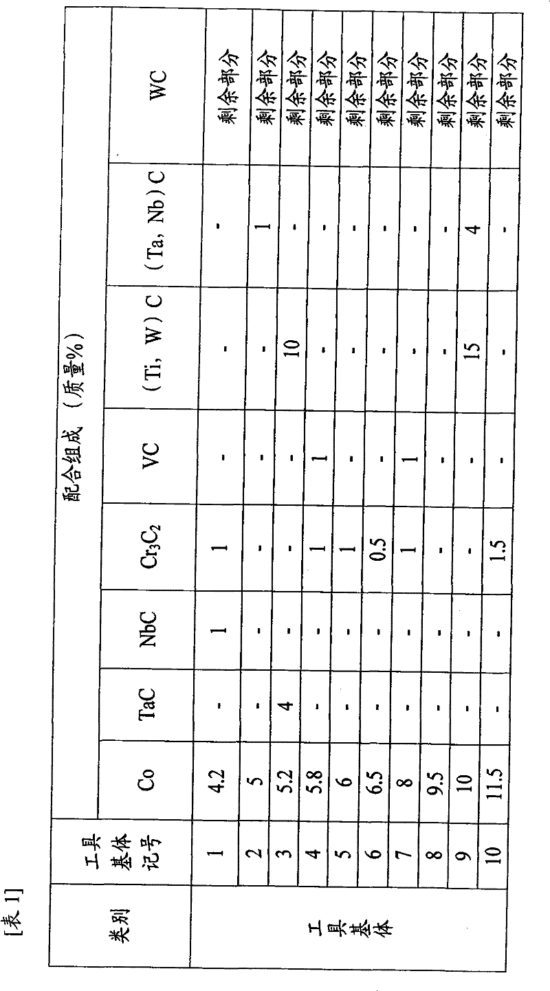
[0040]First, prepare the raw material powders shown in Table 1, which all have a predetermined average particle diameter in the range of 1 to 3 μm, and prepare mixed powders with the compounding composition shown in Table 1, and wet-mix this with a ball mill for 72 hours. After drying, press molding with a pressure of 100 MPa to form round rod compacts with diameters of 10 mm and 8 mm, and sinter these round rod compacts to produce a sintered body. In addition, the outer diameter of the groove forming part is processed to 8 mm, 6mm size, at this time, with respect to the outer peripheral edge and the edge of the blade, the air blasting treatment using SiC abrasive grains with a grain size of #600 and the finish grinding process of 30 μm or more using a diamond whetstone with a grain size of #1200, Thus, tool bases 1 to 5 with an outer diameter of 8 mm and tool bases 6 to 10 with an outer diameter of 6 mm were manufactured.

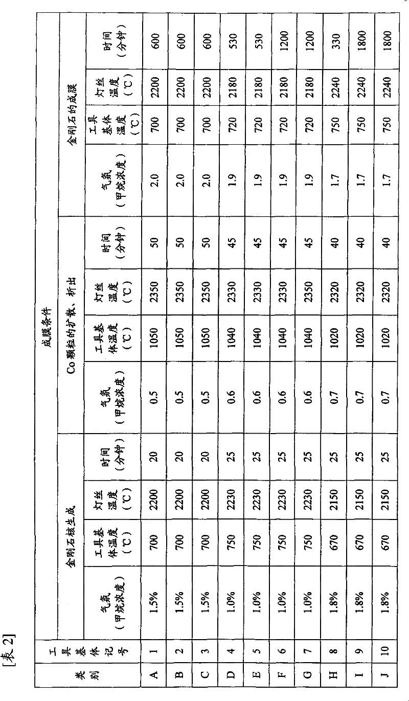
[0041] Then, with a solution of sulfuric acid, hydro...


PUM

PropertyMeasurementUnit
The average particle sizeaaaaaaaaaa

Abstract

The invention provides a diamond coating and cutting element, which has anexcellent adhesiveness in the cutting process of materials hard to be cut like aluminium alloys or graphites, CFRP materials and performs excellent wear resistance during a long-term use. Diamond films in thickness of 5-30Mum are coated on the surface of the diamond coating and cutting element composed by tungsten carbide-based hard alloys or titanium carbonitride-based cermet. Co particles with average diameter of 5-200nm are precipitated at the diamond film side of interface portion between the element body and the diamond films, and the proportion of Co particles is 0.1-20 atom%.

Description

technical field [0001] The present invention relates to a diamond-coated cutting tool in which a diamond film is coated on the surface of a tool substrate (hereinafter, simply referred to as a tool substrate) composed of tungsten carbide (WC)-based cemented carbide or titanium carbonitride-based cermet. The tool, in particular, relates to a diamond-coated cutting tool (hereinafter referred to as a diamond-coated cutting tool) which exhibits excellent wear resistance in long-term use in the cutting of difficult-to-cut materials such as CFRP materials, high-Si aluminum alloys, and graphite. overwrite tool). Background technique [0002] In the past, diamond-coated tools with a diamond film coated on the surface of the tool substrate are known, but there are the following problems in the conventional diamond-coated tools: when forming a film of diamond, due to the tool substrate and diamond during the cooling process after film formation The difference in the thermal expansion...

Claims


Application Information

Patent Timeline
IPC IPC(8): B23B27/20C23C16/27C23C16/02
Inventor 高冈秀充千叶一大岛知
Owner MITSUBISHI MATERIALS CORP
Why Eureka
Try Eureka