System for combined cycle mechanical drive in cryogenic liquefaction processes

A component and expander technology, applied in liquefaction, refrigeration and liquefaction, solidification, etc.

Inactive Publication Date: 2011-09-28
海威气体系统公司
View PDF13 Cites 4 Cited by
  • Summary
  • Abstract
  • Description
  • Claims
  • Application Information

AI Technical Summary

Problems solved by technology

At first glance, this may seem like a complicating factor when using these processes for applications that require minimizing equipment weight and size

Method used


Image

  • System for combined cycle mechanical drive in cryogenic liquefaction processes
  • System for combined cycle mechanical drive in cryogenic liquefaction processes

Examples


Embodiment Construction

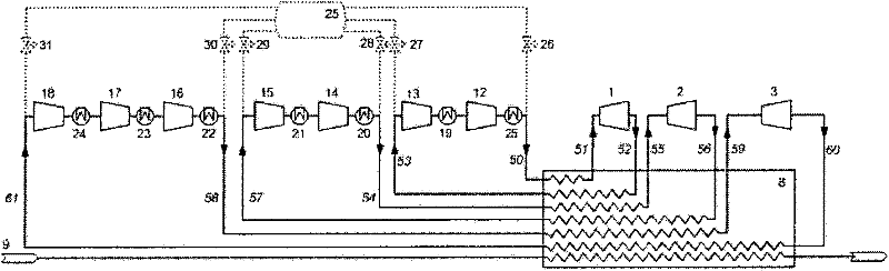
[0014] Such as figure 1 As shown, this refrigeration assembly includes three different refrigeration circuits:

[0015] The high-temperature circuit, shown here with two compressors 12 , 13 or compressor stages and one expander 1 or expander stage, only the compressor and expander respectively are labeled in the following. This is the base case for all three circuits, but if the process advantage is evident, the layout can be made with a different number of compressor or expander units, depending on process requirements or other criteria. This high temperature circuit is used for overheating cooling.

[0016] An intermediate temperature circuit is used to condense the LNG, and this circuit usually consists of two compressors 14, 15 and an expander 2; and

[0017] In the basic case, the cryogenic circuit likewise consists of three compressors 16 , 17 , 18 and an expander and is used for subcooling the LNG.

[0018] Further information on this refrigeration assembly is found ...


PUM


Abstract

A system for producing liquefied and sub-cooled natural gas by means of a refrigeration assembly using a single phase gaseous refrigerant comprises at least two expanders; a compressor assembly; a heat exchanger assembly for heat absorption from natural gas; and a heat rejection assembly, in which the expanders are arranged in expander loops and the refrigerant to the respective expander is served in a compressed flow by means of the compressor assembly having compressors or compressor stages enabling adapted inlet and outlet pressures for the respective expander. According to the present the expanders and compressors assembly are assembled in two mechanically connected compressor and expander packages (200, 300) of which one is driven by a gas turbine (201) and the other is driven by a steam turbine (301), the steam primarily being generated by exhaust gases from the gas turbine in a waste heat recovery unit (202), and in that the expanders and compressors assemblies are distributed between the two compressor and expander packages to optimize the steam utilization and to balance the power generated by the gas turbine and the steam turbine.

Description

Background technique [0001] Over the years, various variations of the Brayton cooling cycle have been continuously developed and described in the patent literature. For example, the characteristics of the original single expander system were shown to favor processes utilizing cooling applications rather than liquefaction due to the fact that the refrigerant remains a single phase throughout the cycle and is therefore easier to accommodate single phase loads such as gas cooling craft. [0002] However, although the traditional Brayton process does not do as well in terms of liquefaction power as the cascade process, mixed refrigerant process and other large-scale liquefaction systems, it has gained some popularity due to its simplicity, robustness and flexibility, And also for liquefaction, for example in the production of liquefied natural gas (LNG). Especially for smaller plants, the simple Brayton system has proven to be practicable. [0003] Most of the factors mentioned...

Claims


Application Information

Patent Timeline
Patent Type & Authority Applications(China)
IPC IPC(8): F25J1/02
CPCF25J1/0282F25J1/0283F25J1/029F25J1/0298F25J2230/20F25J1/0288F25J1/0242F25J2240/82F25J1/005F25J1/0207F25J1/0022F25J1/0279F25J1/0289F25J2270/16
Inventor 拉尔斯·霍尔利克比约恩·哈拉尔德·豪克戴尔
Owner 海威气体系统公司
Why Eureka
Try Eureka