Improved aeration well for in-situ remediation of polluted underground water and remediation method

An in-situ repair and groundwater technology, applied in the direction of oxidized water/sewage treatment, etc., can solve the problems of inapplicability of sites with high pollutant concentrations and long repair time, so as to reduce repair costs and maintenance costs, reduce The effect of lateral diffusion and simple process

Inactive Publication Date: 2011-10-19
JILIN UNIV
View PDF2 Cites 9 Cited by
  • Summary
  • Abstract
  • Description
  • Claims
  • Application Information

AI Technical Summary

Problems solved by technology

This method is a widely applicable and cost-effective remediation method, but the time required for remediation is too long, and it is not suitable for sites with high pollutant concentrations [Reference 5: Langwalt J H, Puhakka J A. On-site biological remediation of contaminated groundwater: a review[J].Environmental Pollution, 2000, 109:187-19. Document 6: Lin CW, Cheng Y W, Tsai S L.Multi-substrate biodegradation kinetics of MTBE and BTEX mixtures by Pseudomonas aeruginosa[ J]. Process Biochemistry, 2007, 42(8): 1211-1217.]

Method used


Image

  • Improved aeration well for in-situ remediation of polluted underground water and remediation method
  • Improved aeration well for in-situ remediation of polluted underground water and remediation method
  • Improved aeration well for in-situ remediation of polluted underground water and remediation method

Examples


Embodiment 1

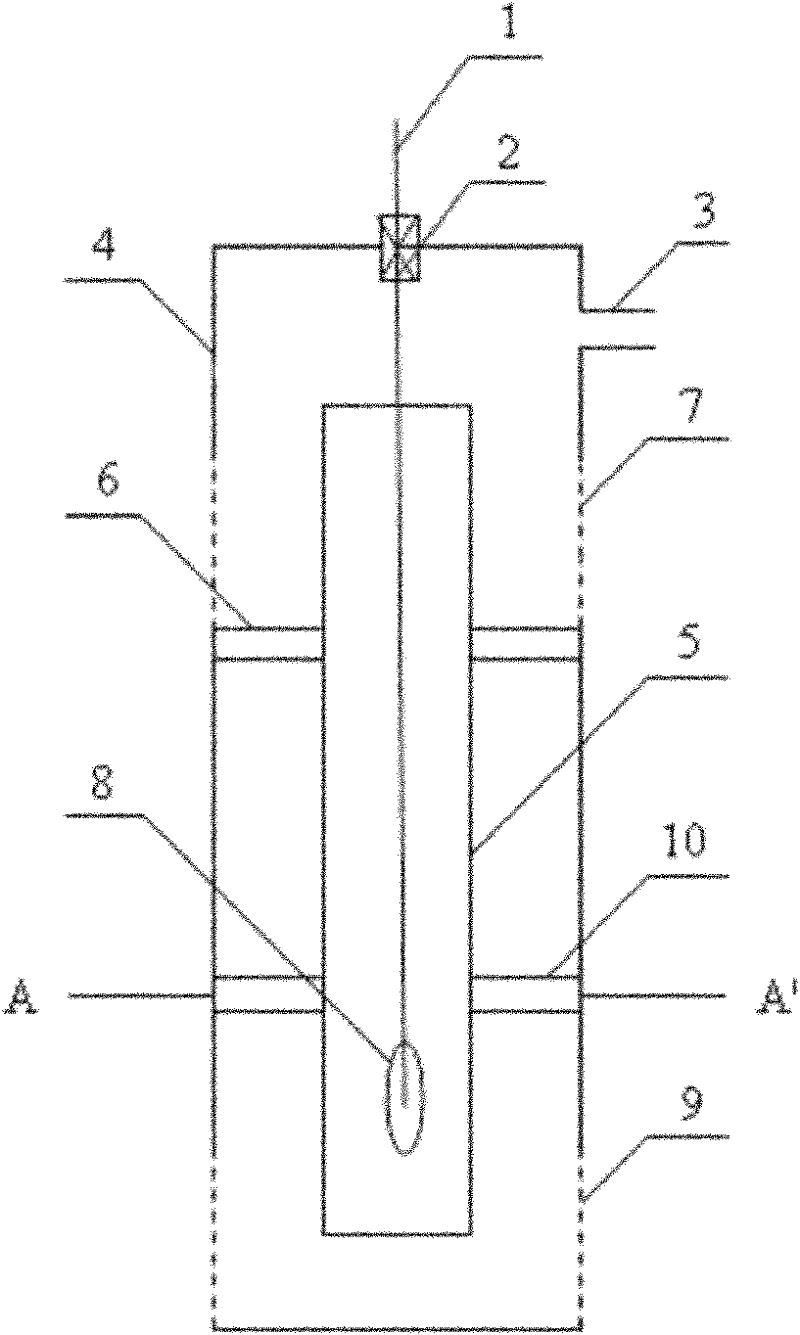
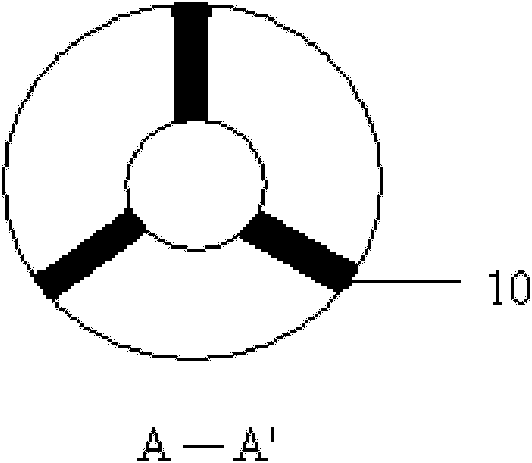
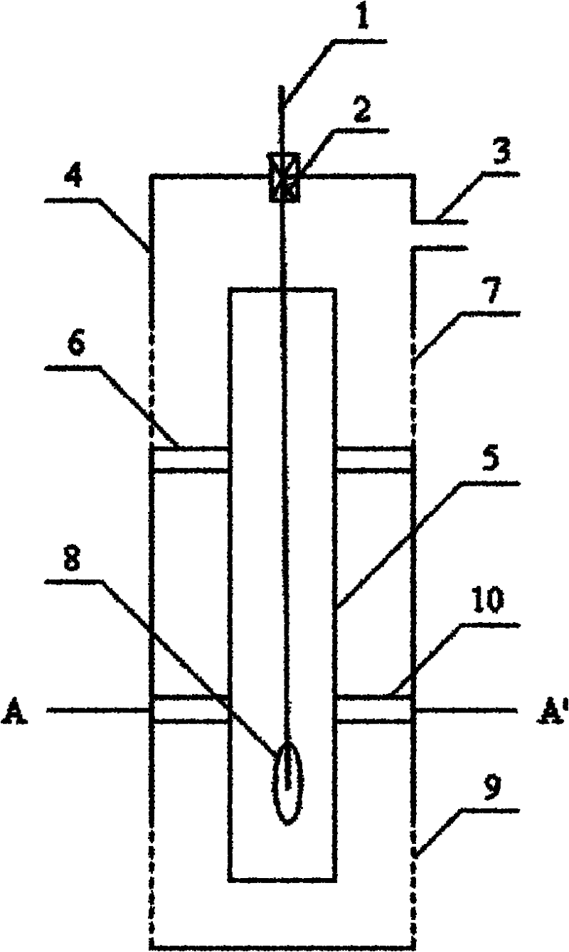
[0037] The improved aeration well for repairing polluted groundwater in situ is that the inner well pipe 5 is set inside the outer well pipe 4, and the inner well pipe is fixed in the outer well pipe 4 by the upper fixing bracket and the lower fixing bracket 10, and the inner well pipe The lower part of 5 is equipped with an aeration head 8, and the aeration head 8 is connected with the aeration pump through the aeration pipe 1 and the regulating valve 2 fixed on the top of the outer well pipe 4. The air hole 3 is connected to the polluting gas monitor, the top of the inner well pipe 5 is lower than the vent hole 3, and the lower part of the upper vent hole 3 of the outer well pipe 4 is provided with an upper flower tube 7, and the top hole of the upper flower tube 7 is lower than the inner well pipe. Well pipe 5, the lower section of outer well pipe 4 is provided with lower floral tube 9, the top hole of lower floral tube 9 is higher than the bottom end surface of inner well p...

Embodiment 2

[0050] The improved aeration well for repairing polluted groundwater in situ is that the inner well pipe 5 is set inside the outer well pipe 4, and the inner well pipe is fixed in the outer well pipe 4 by the upper fixing bracket and the lower fixing bracket 10, and the inner well pipe The lower part of 5 is equipped with an aeration head 8, and the aeration head 8 is connected with the aeration pump through the aeration pipe 1 and the regulating valve 2 fixed on the top of the outer well pipe 4. The air hole 3 is connected to the polluting gas monitor, the top of the inner well pipe 5 is lower than the vent hole 3, and the lower part of the upper vent hole 3 of the outer well pipe 4 is provided with an upper flower tube 7, and the top hole of the upper flower tube 7 is lower than the inner well pipe. Well pipe 5, the lower section of outer well pipe 4 is provided with lower floral tube 9, the top hole of lower floral tube 9 is higher than the bottom end surface of inner well p...

Embodiment 3

[0063] The improved aeration well for repairing polluted groundwater in situ is that the inner well pipe 5 is set inside the outer well pipe 4, and the inner well pipe is fixed in the outer well pipe 4 by the upper fixing bracket and the lower fixing bracket 10, and the inner well pipe The lower part of 5 is equipped with an aeration head 8, and the aeration head 8 is connected with the aeration pump through the aeration pipe 1 and the regulating valve 2 fixed on the top of the outer well pipe 4. The air hole 3 is connected to the polluting gas monitor, the top of the inner well pipe 5 is lower than the vent hole 3, and the lower part of the upper vent hole 3 of the outer well pipe 4 is provided with an upper flower tube 7, and the top hole of the upper flower tube 7 is lower than the inner well pipe. Well pipe 5, the lower section of outer well pipe 4 is provided with lower floral tube 9, the top hole of lower floral tube 9 is higher than the bottom end surface of inner well p...


PUM


Abstract

The invention relates to an improved aeration well for in-situ remediation of polluted underground water and a remediation method. In the improved aeration well, an inner well tube is sleeved in an outer well tube; the inner well tube is fixed in the outer well tube by using an upper fixed bracket and a lower fixed bracket; an aeration head is arranged at the lower part of the inner well tube and is connected with an aeration pump through an aeration pipe; an exhaust hole is arranged at the upper part of the outer well tube and is connected with a contaminated gas monitor; an upper shock tube is arranged at the lower part of the exhaust hole at the upper part of the outer well tube; a top hole of the upper shock tube is lower than the inner well tube; a lower shock tube is arranged on the lower section of the outer well tube; a top hole of the lower shock tube is higher than the bottom end face of the inner well tube; and the bottom end face of the outer well tube is in contact with a base plate of an underground water layer. The invention has the advantage that the transverse diffusion of the pollutants is reduced by increasing the vertical flow of underwater. Compared with the traditional underground water aeration technology and extraction treatment technology, the remediation method has a simpler process, the improved aeration well can continuously operate by conventional maintenance, the remediation efficiency is improved and the remediation cost and the maintenance cost are reduced.

Description

technical field [0001] The invention relates to a treatment method for groundwater pollution, in particular to an improved aeration well for in-situ restoration of polluted groundwater and a restoration method. Background technique [0002] Groundwater pollution in my country is becoming more and more serious. Although there is certain economic strength and technical support for pollution control and treatment, due to its concealment, complexity, characteristics that are difficult to control and treatment, and time-consuming, treatment and restoration costs are huge. Groundwater The remediation of pollution is less carried out. [0003] Groundwater in-situ remediation technology can minimize the exposure of pollutants and the disturbance to the surrounding environment, so it has attracted widespread attention in recent years. The in-situ remediation techniques of groundwater mainly include: (1) In-situ physical remediation. For example: groundwater aeration technology (air ...

Claims


Application Information

Patent Timeline
IPC IPC(8): C02F1/72
Inventor 赵勇胜屈智慧周睿焦立娜王冰
Owner JILIN UNIV
Why Eureka
Try Eureka