Method and apparatus for improved resolution chromatography

a chromatography and resolution technology, applied in the field of column chromatography, can solve the problems of serious parabolic flow, significant decrease in separation performance, and uneven sample distribution across the column radial cross section, and achieve the effect of low drag on flow

Active Publication Date: 2013-11-28
UNIVERSITY OF WESTERN SYDNEY +1
View PDF2 Cites 0 Cited by
  • Summary
  • Abstract
  • Description
  • Claims
  • Application Information

AI Technical Summary

Benefits of technology

[0083]The material of the outlet frit may be conventional frit material as used in LC, e.g. steel. Thus, the frit may simply be configured in the split manner described herein to split the eluate flow that flows through it. For example, the frit material, thickness (depth), and porosity may be conventional as used in LC systems. For example, a frit of typical thickness of 0.25 to 2 mm may be used. For example, a frit with 2 μm porosity may be used. The non-porous body of the split frit embodiments is preferably made of a plastics or polymer, e.g. PTFE, ETFE, PEEK or Kel-F, more preferably PEEK, or may be made of metal, e.g. stainless steel. Such non-porous materials may also be provided as a thin layer or coating on one or more surfaces of one or more frit sections that abut another frit section to provide a flow barrier. The non-porous flow barrier alternatively could be made of a metal. Such a metal barrier could be formed by sputtering as a thin layer or coating on one or more surfaces of one or more frit sections that abut another frit section. Such thin layer or coating flow barriers may have an advantage of low drag on the flow.
[0084]The width (i.e. measured in the radial direction) of the flow barrier or non-porous body is preferably small compared to the width of the frit sections, i.e. is preferably lower than the width of the frit sections. Thus, any possible drag on the flow of separated components that may be caused by the presence of the flow barrier in the flow, or any dead zone effects behind the flow barrier, may thereby be minimised. It will be appreciated, however, that the barrier should not be so thin that segregation of the flow into separate portions is not effectively achieved.

Problems solved by technology

Use of a distributor improved the uniformity of the flow velocity across the radial cross section of the bed, however, at the cost increasing the axial dispersion, which ultimately led to a substantial decrease in separation performance.
Irrespective of the frit porosity or whether or not a distributor was employed, sample distribution was not uniform across the column radial cross section.
If not, with a frit having a narrower diameter than that of the column, very serious parabolic flow results.
It may be intuitive to the chromatographer that the frit diameter must equal that of the column internal diameter, but it is not always possible to achieve, particularly in the case of columns prepared by axial compression where the head fitting is inside the column itself.
While excellent separation efficiency was observed by Shalliker et. al. when utilising the CPI technique, it should be pointed out that such a sample introduction method is tedious, and prone to be destructive to the column bed.
Hence the technique is not suited to routine applications.
Furthermore, whilst central point injections allow for the most efficient means of solute transport along the column since such injections allow the sample to be concentrated in a local, central zone within the most efficiently packed region of the column, modern columns have effectively prevented the use of such injection techniques, since valve injection disperses sample across the column as it enters by a frit and distributor at the top of the column.
They also showed that a disturbed region of column packing extends into the column causing serious band broadening and peak distortion.
Both these wall effects contribute greatly to decreasing the efficiency of migration.
Hence, longer columns are necessary to effect separation, which results in an increase in time, possibly resulting also in a decrease in the potential flow velocity in order to accommodate a longer column.

Method used


Image

  • Method and apparatus for improved resolution chromatography
  • Method and apparatus for improved resolution chromatography
  • Method and apparatus for improved resolution chromatography

Examples


examples

[0173]Details of various experiments and results are given below to further illustrate the invention by way of additional examples.

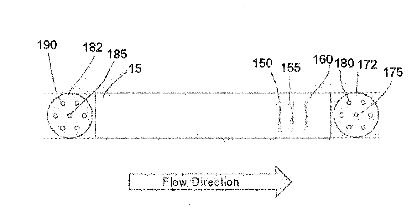
[0174]The experiments were conducted on a 100×21 mm steel column packed with 12 μm pentafluorophenyl-silica stationary phase particles. All experiments testing the different column hardware configurations were undertaken on the same column, with head fittings interchanged as appropriate. The experiments conducted used: (1) conventional column (single inlet port and single outlet port); (2) conventional column inlet fitting (single inlet port) with segmented flow outlet fitting (4 ports: 1 central port and 3 peripheral ports); and (3) curtain flow column inlet fitting (4 ports: 1 central port and 3 peripheral ports) with segmented flow outlet fitting (4 ports: 1 central port and 3 peripheral ports). Injection of toluene, propyl benzene and butyl benzene, in a 30 / 70 water / methanol mobile phase (250 μL) was used to test performance for these three modes of ...


PUM


Abstract

An apparatus and a method are provided for column chromatography, which provide improvements in separation resolution and detection sensitivity, comprising a chromatography column having an inlet and an outlet, wherein the inlet is configured to introduce a flow of mobile phase into the column carrying a sample, wherein the inlet is further configured to introduce the flow of mobile phase into the column in at least two separate portions which are independently controllable, and to introduce the portions into different radial regions of the column, such that the portions flow longitudinally through the column in different radial regions. The sample preferably is contained in one of the portions, especially a central portion, in a higher concentration than in the other portion(s). Preferably the flow velocities of the portions are independently controllable.

Description

CROSS-REFERENCE TO RELATED APPLICATIONS[0001]This application claims priority to U.S. provisional patent application Ser. No. 61 / 519,733 filed May 26, 2011, entitled “Improved Resolution Chromatography System,” which application is incorporated herein by reference in its entirety.FIELD OF THE INVENTION[0002]This invention relates to the field of column chromatography.BACKGROUND OF THE INVENTION[0003]Chromatography columns have been extensively developed and are used routinely in both analytical and preparative chromatography. As is well known, the separation in a chromatography column of a sample (also termed an analyte or solute) comprising a mixture of components is achieved by dissolving the sample in an eluant to form a fluid mobile phase and passing the mobile phase through a stationary phase typically packed within a tubular column, thereby causing the sample to separate into its components due to the differences in the partitioning between the mobile and stationary phases of ...

Claims


Application Information

Patent Timeline
Patent Type & Authority Applications(United States)
IPC IPC(8): B01D15/22
CPCB01D15/22B01D15/10B01D15/18G01N30/60G01N30/6004G01N30/6017G01N30/603G01N30/6086
Inventor RITCHIE, HARALDSHALLIKER, ROSS ANDREW
Owner UNIVERSITY OF WESTERN SYDNEY
Why Eureka
Try Eureka