
Manufacturing method of electrolytic capacitor

A technology of electrolytic capacitors and manufacturing methods, applied in the direction of electrolytic capacitor manufacturing, electrolytic capacitors, capacitors, etc., can solve the problems of electrolytic capacitors, such as electrostatic capacity, electrical characteristics and reliability reduction, and achieve the effect of high electrostatic capacity and reliability

Active Publication Date: 2015-07-29
PANASONIC INTPROP MANAGEMENT CO LTD
View PDF2 Cites 0 Cited by
  • Summary
  • Abstract
  • Description
  • Claims
  • Application Information

AI Technical Summary

Problems solved by technology

[0006] However, in the above-mentioned method of manufacturing an electrolytic capacitor, there is a problem that the electrical characteristics and reliability of the electrolytic capacitor such as electrostatic capacity, ESR, and leakage current (LC) are lowered due to heat treatment after the notch forming step.

Method used


Image

  • Manufacturing method of electrolytic capacitor
  • Manufacturing method of electrolytic capacitor
  • Manufacturing method of electrolytic capacitor

Examples


Embodiment 1

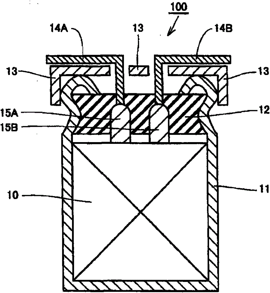
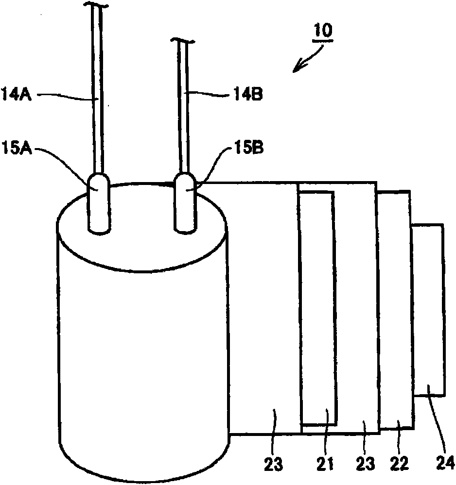
[0039]First, an aluminum foil whose surface has been roughened by etching is immersed in a chemical conversion solution containing an ammonium adipate solution, and a voltage is applied to form a dielectric film on the surface of the aluminum foil. Then, the aluminum foil on which the dielectric coating was formed was cut to produce anode foil 21 on which the dielectric coating was formed. Thereafter, lead wires 14A, 14B serving as terminals are connected to anode foil 21 and cathode foil 22 made of aluminum foil via lead tabs 15A, 15B, respectively. It should be noted that copper-clad steel wires are used for the lead wires 14A, 14B. Then, the anode foil 21 and the cathode foil 22 were wound through a separator 23 containing 90% by weight of vinylon fiber and 10% by weight of polyvinyl alcohol (PVA), and the winding was stopped with a winding stop tape 24 to produce a capacitor element 10 .

[0040] Next, the capacitor element 10 was immersed in a 25° C. chemical conversion ...

Embodiment 2

[0045] An electrolytic capacitor was fabricated by the same method as in Example 1 except that the separator 23 containing 90% by weight of nylon fibers and 10% by weight of PVA was used as the separator.

Embodiment 3

[0047] An electrolytic capacitor was produced in the same manner as in Example 1 except that the separator 23 containing 90% by weight of acrylic fiber and 10% by weight of PVA was used as the separator.


PUM

PropertyMeasurementUnit
diameteraaaaaaaaaa
heightaaaaaaaaaa
thermal degradation temperatureaaaaaaaaaa

Abstract

A method of manufacturing an electrolytic capacitor according to the present invention includes the steps of: forming a capacitor element by winding an anode foil having a roughened surface on which a dielectric film is formed, a cathode foil, and a separator containing a synthetic fiber and a water-soluble binder; immersing the capacitor element in a chemical conversion solution containing water as a main solvent for re-chemical conversion; subjecting the capacitor element subjected to re-chemical conversion to first heat treatment at a temperature of not less than 60° C. and less than 100° C.; and subjecting the capacitor element subjected to the first heat treatment to second heat treatment at a temperature of not less than 150° C. and less than a melting point of the synthetic fiber.

Description

technical field [0001] The invention relates to a method for manufacturing an electrolytic capacitor, in particular to a method for manufacturing an electrolytic capacitor in which synthetic fibers are used as separators. Background technique [0002] In recent years, along with digitization and higher frequency of electronic equipment, there has been a demand for electrolytic capacitors that are small in size, large in capacity, and have low impedance even in the high frequency range. [0003] A wound type electrolytic capacitor has been developed as an electrolytic capacitor that meets the above requirements. A wound electrolytic capacitor has a configuration in which liquid or solid electrolyte is impregnated in a gap between an anode foil and a cathode foil wound through a separator. With such a winding structure, a small and large-capacity electrolytic capacitor can be realized. [0004] In order to improve the performance of this electrolytic capacitor, various studi...

Claims


Application Information

Patent Timeline
Patent Type & Authority Patents(China)
IPC IPC(8): H01G9/00H01G9/02
CPCY10T29/417H01G9/02H01G9/0029H01G9/048
Inventor 古川刚士小柳健太郎
Owner PANASONIC INTPROP MANAGEMENT CO LTD
Features
  • Generate Ideas
  • Intellectual Property
  • Life Sciences
  • Materials
  • Tech Scout
  • Unparalleled Data Quality
  • Higher Quality Content
  • 60% Fewer Hallucinations
Learn More