
Electro-spray disinfection equipment

A sterilization equipment, electrospray technology, applied in electrostatic spraying device, spraying device, preservation of meat/fish through radiation/electrical treatment, etc., can solve problems such as inactivation, high technical requirements for equipment, bacterial breakdown, etc., and achieve structural Simple, good sterilization effect, convenient operation

Active Publication Date: 2011-10-26
ZHEJIANG HAOCHUANG BIOTECH
View PDF2 Cites 13 Cited by
  • Summary
  • Abstract
  • Description
  • Claims
  • Application Information

AI Technical Summary

Problems solved by technology

[0003] However, the technical solutions implemented in the above-mentioned patents all use high pulse voltage in the liquid to form a high-intensity pulse electric field, so that the bacteria in the liquid are electrically broken down by the high-intensity pulse electric field, and eventually lead to inactivation.
The implementation of this technical solution must first provide a high-intensity pulse voltage, so there is high energy consumption and high technical requirements for equipment. Of course, there are certain risk factors; The liquid with the same parameters gets the same pulse electric field strength, and the physical and chemical parameters of the beverage may change at any time in the beverage production line, resulting in unstable sterilization effect
[0004] Since the liquid is applied with the same voltage, the change of the physical parameters of the liquid, such as conductivity, dielectric constant, etc., will greatly affect the electric field strength in the liquid, thus affecting the sterilization effect
At present, most of the research on the sterilization of high-voltage pulsed electric field has not solved this important problem, so far, the sterilization of high-voltage pulsed electric field has not been applied in the actual beverage production line.

Method used


Image

  • Electro-spray disinfection equipment
  • Electro-spray disinfection equipment
  • Electro-spray disinfection equipment

Examples


Embodiment 1

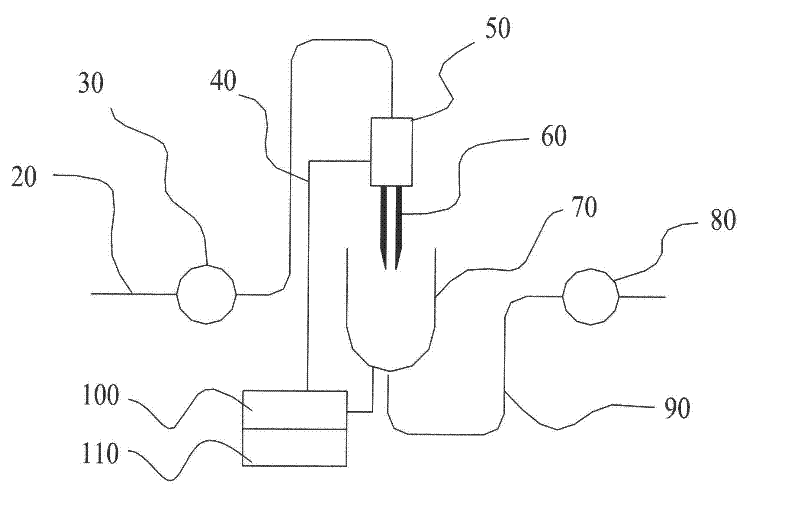
[0021] according to figure 1 The structure shown is assembled with electrospray sterilization equipment, including a voltage device 100 and a voltage connector sleeve 50. The positive electrode of the voltage device 100 is connected to the voltage connector sleeve 50 through a cable 40, and the outlet of the voltage connector sleeve 50 is a hollow capillary tube emitting The needle 60, wherein the voltage connector sleeve 50 is made of metal iron. The voltage of the voltage device 100 is a pulse voltage, wherein the voltage value is 100V; the inlet of the voltage joint sleeve 50 is connected with the input pipeline 20 and the feed delivery pump 30; the width of the outlet end of the hollow capillary emitting needle 60 is 10 mm; The outlet end of the capillary emission needle 60 is opposite to the collection container 70, and the collection container 70 is connected to the discharge delivery pump 80 through the output pipe 90, and the collection container 70 is connected to the...

Embodiment 2

[0025] according to figure 1 The structure shown is assembled with electrospray sterilization equipment, including a voltage device 100 and a voltage connector sleeve 50. The positive electrode of the voltage device 100 is connected to the voltage connector sleeve 50 through a cable 40, and the outlet of the voltage connector sleeve 50 is a hollow capillary tube emitting The needle 60, wherein the voltage connector sleeve 50 is made of metal iron. The voltage of the voltage device 100 is a random pulse voltage, the voltage value of which is 1000V; the inlet of the voltage joint sleeve 50 is connected with the input pipeline 20 and the feeding pump 30; the width of the outlet end of the hollow capillary emitting needle 60 is 8 mm; The outlet end of the hollow capillary emitting needle 60 is opposite to the receiving collection container 70, the collection container 70 is connected to the discharge delivery pump 80 through the output pipe 90, and the collection container 70 is c...

Embodiment 3

[0029] according to figure 1The structure shown is assembled with electrospray sterilization equipment, including a voltage device 100 and a voltage connector sleeve 50. The positive electrode of the voltage device 100 is connected to the voltage connector sleeve 50 through a cable 40, and the outlet of the voltage connector sleeve 50 is a hollow capillary tube emitting The needle 60, wherein the voltage connector sleeve 50 is made of metal iron. The voltage of the voltage device 100 is a unidirectional sine wave voltage, the voltage value of which is 5000V; the inlet of the voltage joint sleeve 50 is connected with the input pipeline 20 and the feeding pump 30; the width of the outlet end of the hollow capillary emitting needle 60 is 0.5 mm; the outlet end of the hollow capillary launch needle 60 is connected to the receiving collection container 70, and the collection container 70 is connected to the discharge delivery pump 80 through the output pipeline 90, and the collecti...


PUM

PropertyMeasurementUnit
Voltage valueaaaaaaaaaa
The inside diameter ofaaaaaaaaaa

Abstract

The invention discloses a processing machinery apparatus used in foodstuff industry, and specifically refers to a disinfection machinery for a liquid beverage and a liquid. According to the invention, one end of a voltage apparatus is connected with a voltage joint sleeve, and the other end of the voltage apparatus is connected with a collection container. An outlet of the voltage joint sleeve ishollow capillary emission needles, and an internal diameter of an outlet end of a hollow capillary emission needle is small. Liquid forms a Taylor cone at the outlet end due to electric field effect,and a high electric field zone is formed on a surface of the Taylor cone. Bacteria passing through the high electric field are fully polarized and thoroughly torn or punctured, so as to finally realize forcible killing of bacteria. The invention has the advantages of simple structure, convenient operation, and better and more thorough sterilization effect. The invention has obvious technical superiority especially in processing of substances that can not be treated under high temperature, high pressure or strong electric field. In addition, the invention can be widely applied to industries offoodstuff and beverage, etc.

Description

technical field [0001] The invention relates to the field of processing machinery in the food industry, in particular to a sterilizing machine for liquid beverages and liquids. technical background [0002] The main principle of high-voltage pulsed electric field technology for food enzyme sterilization is based on the difference in electrical characteristics between cell structures and liquid food systems. When liquid food is placed in an electric field as a dielectric, the cell membranes of microorganisms in the food will be broken down by electricity under the action of a strong electric field, resulting in irreparable perforations or ruptures, which will damage the cell tissue and lead to the inactivation of microorganisms. It is confirmed that under the conditions of pulse electric field intensity of 12-40Kv / cm and pulse time of 20μs-18μs, food can be sterilized effectively, and the double rectangular wave is the most effective. Many scientists have conducted a lot of ...

Claims


Application Information

Patent Timeline
IPC IPC(8): A23L2/50A23L3/32
CPCA23L2/50A23B4/015A23L3/32B05B5/0255
Inventor 朱一心吕婷婷潘小忠
Owner ZHEJIANG HAOCHUANG BIOTECH
Learn More