Variable structure adaptive feed type rope saw

An adaptive and variable structure technology, which is applied in the direction of sawing machine, metal sawing equipment, metal processing equipment, etc., can solve the problems of increasing equipment manufacturing cost, inability to use pipes with different diameters, and narrow use range, so as to improve work stability The effect of increasing the degree of difficulty, increasing the difficulty of the structure, and increasing the cutting speed

Inactive Publication Date: 2011-11-02
HARBIN ENG UNIV
View PDF6 Cites 43 Cited by
  • Summary
  • Abstract
  • Description
  • Claims
  • Application Information

AI Technical Summary

Problems solved by technology

From the diamond wire saw machine products developed at home and abroad, different pipe diameters correspond to different wire saw machines, that is, the wire saw machine series. A wire saw machine with a specification can only cut a fixed range of pipes. Therefore, for The adaptability of the processing object is not strong, which increases the cost of equipment manufacturing
[0008] Chinese patent application (publication number CN101444921A) discloses an underwater wire saw cutting machine, which adopts a triangular fixed feed mechanism. Although the structural arrangement of the three wheels is simple in structure and stable in operation, it largely limits the diameter range
In addition, the clamping device of this patent cannot adjust the clamping space, so it cannot be universally used for pipes of different diameters, thus limiting its scope of application
[0009] Chinese patent application number 200710303952.0 (publication number CN101468440A) discloses a clamping device of an underwater diamond wire saw machine. diameter pipes, and cannot be used for small diameter pipes at the same time, so there is also the problem of narrow use range

Method used


Image

  • Variable structure adaptive feed type rope saw
  • Variable structure adaptive feed type rope saw
  • Variable structure adaptive feed type rope saw

Examples


Embodiment Construction

[0030] Preferred embodiments of the present invention will be described in detail below in conjunction with the accompanying drawings.

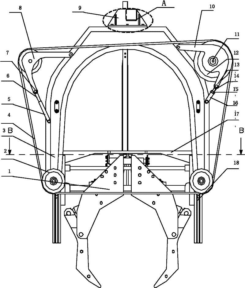
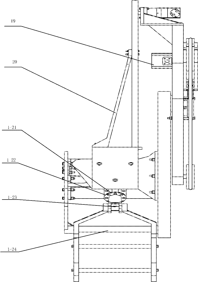
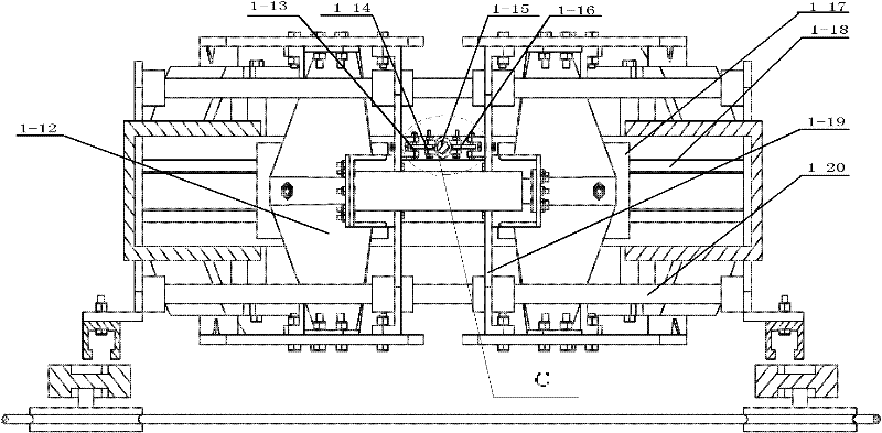
[0031]In the variable structure adaptive feed wire saw machine, the sliding pair is formed by the dovetail groove guide rail 1-18 and the sliding block 1-17, and the sliding pair connects the sliding block 1-17, the rib plate 1-12 and the V The templates 1-9 are connected, so that the main rail device for the movement of the manipulator is formed. Sleeve and polished rod guide rail 1-20 are arranged on connecting plate 1-19 to form auxiliary moving pair, and connect connecting plate 1-19 and V-shaped plate 1-9 by bolt pair to form the main guide device that manipulator moves. Drive the hydraulic cylinder 1-8 and the hydraulic rod 1-10 to push the connecting rod 1-7 connected with the sliding sleeve 1-14, thereby moving the clamping claw. Due to the use of the two-way hydraulic rod 1-10, an auxiliary synchronization mechanism is designed in o...


PUM


Abstract

The invention mainly aims to provide a variable structure adaptive feed type rope saw for cutting composite pipes with different diameters amphibiously. The rope saw consists of a clamping mechanism, a cutting mechanism, a feeding mechanism and a tensioning mechanism; the clamping mechanism comprises a V-shaped plate, the V-shaped plate is formed by folding two mutually independent half plates, each half plate is connected with respective sliding block, and the sliding block and a guide rail I form a sliding pair; the two half plates fixed on respective sliding blocks can move relatively in the radial direction along the guide rail I; the half plates are connected with a hydraulic cylinder respectively, and the hydraulic cylinder is connected with a control system; and the lower ends of the half plates are connected with clamping claws through fixing pins, and the rear ends of the clamping claws are connected with the hydraulic cylinder. The rope saw is suitable for the pipes with diameters of phi 300 to phi 1,500 millimeters, so the diameter range of the cut pipes is greatly expanded; and meanwhile, different cutting speeds can be automatically adjusted according to different cutting states to adapt the rope saw, and the cutting efficiency is improved.

Description

Technical field: [0001] The invention relates to a wire saw machine which can perform cutting operations both on land and underwater. Background technique: [0002] With the development and utilization of the world's marine resources, the research on underwater operation technology and equipment is becoming more and more important. Among them, the submarine pipeline is the main maintenance facility in the process of offshore oil and gas field development, production and oil and gas transportation, and pipeline transportation has become the most important, fastest, most economical and most reliable way in oil and gas transportation. However, with the increase of the service life of the submarine pipeline, due to various reasons such as the harsh working environment, the phenomenon of damage to the submarine pipeline continues to occur. The submarine pipeline is usually a composite pipeline composed of reinforced concrete, polyethylene, grease, foam, asbestos, steel pipe and ...

Claims


Application Information

Patent Timeline
Patent Type & Authority Applications(China)
IPC IPC(8): B23D57/00
Inventor 王茁张维张永锐王立权扬占争张佰正魏金旺杨敏勃
Owner HARBIN ENG UNIV
Why Eureka
Try Eureka