
Engine electric control auxiliary cooling system freeing from engine rotational speed influence

An auxiliary cooling system, engine speed technology, applied in the direction of engine cooling, engine components, machines/engines, etc., can solve the problems of increased engine fuel consumption, limited flow capacity, low engine operating temperature, etc., to overcome the limited flow capacity, Easy to popularize and low cost effect

Inactive Publication Date: 2011-11-02
CATARC TIANJIN AUTOMOTIVE ENG RES INST CO LTD
View PDF7 Cites 21 Cited by
  • Summary
  • Abstract
  • Description
  • Claims
  • Application Information

AI Technical Summary

Problems solved by technology

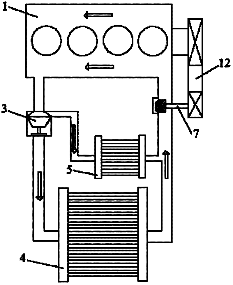
The rotational speed of the mechanical water pump 7 and the rotational speed of the engine 1 have a fixed speed ratio relationship, so the flow rate of the coolant cannot be adjusted according to the actual temperature of the engine coolant
[0003] According to the principle of the engine cooling system, when the engine coolant temperature is high, in order to prevent the engine from overheating, the water pump must provide a large enough coolant flow rate; the first consideration of the water pump selection is to meet the most severe conditions in the actual use of the vehicle. The cooling condition is usually the low-speed and full-load condition of the engine. Therefore, the selection of the water pump is generally to meet the cooling requirements of the engine at low and medium speed conditions; however, when the engine speed is high, especially in light load conditions, The coolant flow provided by the water pump is too large, which will take away too much heat, making the engine operating temperature lower than the ideal target temperature; in addition, in order to shorten the warm-up time when the engine is cold started, it is necessary to reduce the coolant flow as much as possible, otherwise , prolonged warm-up increases engine fuel consumption and worsens emission levels
[0004] In the case of using a traditional mechanical engine cooling system, when the engine 1 is stopped when it is in a hot state, the mechanical water pump 7 will stop, and the waste heat of the engine 1 cannot be released through the cooling system, resulting in a heat soak effect, which will affect the engine 1 in the long run Reliability of mechanical components; in addition, in cold weather, the driver usually turns on the cabin heater, even when the engine is parked, it is necessary to keep the engine 1 running so that the mechanical water pump 7 can provide high-temperature coolant to the heater core 5 , thus increasing the idling time of engine 1, resulting in increased fuel consumption and emissions of engine 1
[0005] At present, some companies have begun to develop and even apply electronic water pumps. Electronic water pumps are used to control the speed of electronic water pumps to achieve the separation of cooling water flow control and engine speed. However, compared with mechanical water pumps, electronic water pumps are more expensive and reliable. The performance is poor, and the control system is complicated. In addition, due to the limitation of the motor power, its flow capacity is limited, which cannot meet the requirements of medium and large displacement engines.

Method used


Image

  • Engine electric control auxiliary cooling system freeing from engine rotational speed influence
  • Engine electric control auxiliary cooling system freeing from engine rotational speed influence
  • Engine electric control auxiliary cooling system freeing from engine rotational speed influence

Examples


Embodiment approach 1

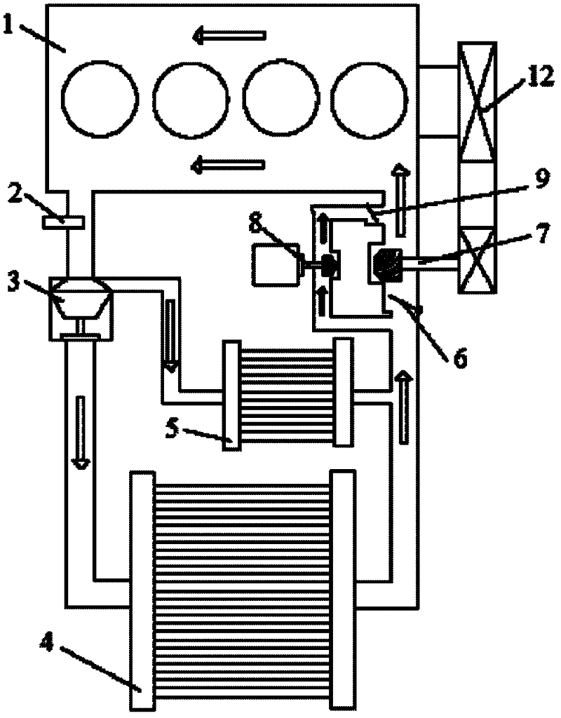
[0035]When the engine is cold started, the temperature of the engine 1 is relatively low, and it takes a certain time to reach the normal temperature. At this stage, the mechanical water pump 7 is running with the engine 1 . When the electronic water pump controller 10 detects that the engine outlet water temperature is low through the engine coolant temperature sensor 2, and detects that the engine 1 is running through the engine controller 11, it controls the electronic water pump 8 not to operate, and the main valve of the thermostat 3 is closed. state; under the action of the coolant pressure difference, the second one-way valve 9 at the outlet of the electronic water pump is closed, and the first one-way valve 6 at the inlet of the mechanical water pump is fully opened; the coolant pressurized by the mechanical water pump 7 flows through the engine 1 respectively , 3 secondary valves of the thermostat and the warm air core 5 get back to the 7 inlets of the mechanical wate...

Embodiment approach 2

[0037] After the engine is warmed up, the mechanical water pump 7 runs with the engine 1. When the coolant temperature at the engine outlet reaches temperature B, the main valve of the thermostat 3 is opened, and part of the coolant flows through the radiator 4, and the other part of the coolant flows through the heater core. child 5. As the temperature rises, when the electronic water pump controller 10 detects that the engine outlet water temperature exceeds the threshold temperature D through the engine coolant temperature sensor 2, and detects that the engine 1 is running through the engine controller 11, the electronic water pump 8 starts to work in the middle mode. Under the action of pressure, the second check valve 9 at the outlet of the electronic water pump opens, and the flow rate of the system coolant is equal to the sum of the flow rate of the mechanical water pump 7 and the flow rate of the electronic water pump 8 . When the electronic water pump controller 10 de...

Embodiment approach 3

[0039] When the operating temperature of the engine is high, the electronic water pump 8 works at a medium speed. When the electronic water pump controller 10 detects that the engine outlet coolant temperature rises to a threshold temperature F higher than the threshold temperature D through the engine coolant temperature sensor 2, the electronic water pump 8 starts to work at full speed, and the flow rate of the system coolant is equal to the sum of the flow rate of the mechanical water pump 7 and the flow rate of the electronic water pump 8 . When the electronic water pump controller 10 detects through the engine coolant temperature sensor 2 that the engine outlet coolant temperature drops to a threshold temperature E which is lower than the threshold temperature F but higher than the threshold temperature D, the electronic water pump 8 starts to work at a medium speed.


PUM


Abstract

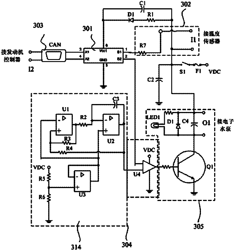
The invention discloses an engine electric control auxiliary cooling system freeing from an engine rotational speed influence. The engine electric control auxiliary cooling system comprises an electronic water pump which is sequentially connected in series with an engine, a thermolator, a heat radiator and an air heating core and is connected in parallel with a mechanical water pump; the outlet of the electronic water pump and the inlet of the mechanical water pump are respectively provided with a one-way valve; the electronic water pump is provided with an electronic water pump controller; the signal input end of the electronic water pump controller is respectively connected with an engine cooling liquid temperature sensor on the water outlet of the engine and an engine controller; and the signal output end of the electronic water pump controller is connected with the electronic water pump. According to the engine electronic control auxiliary cooling system provided by the invention, the power requirement on the mechanical water pump from the cooling system is reduced, thereby the volume and layout requirements of the mechanical water pump are reduced; the application of the engine cooling system provided by the invention adopts an operation mode of mainly relying on the mechanical water pump supplemented by the electronic water pump, and has the advantages of convenience for operation, high reliability, low cost, good applicability and easiness for popularization.

Description

technical field [0001] The invention relates to an engine cooling system, in particular to an engine electronically controlled auxiliary cooling system which is not affected by the engine speed. Background technique [0002] At present, most of the water pumps in the vehicle engine cooling system use mechanical water pumps, such as figure 1 As shown, a mechanical transmission 12 is adopted between the mechanical water pump 7 and the engine 1. As long as the engine 1 is running, the mechanical water pump 7 will run. The main and auxiliary valves respectively enter the radiator 4 and the warm air core 5, and then collectively enter the inlet of the mechanical water pump 7. The rotational speed of the mechanical water pump 7 and the rotational speed of the engine 1 have a fixed speed ratio relationship, therefore, the flow rate of the coolant cannot be adjusted according to the actual temperature of the engine coolant. [0003] According to the principle of the engine cooling...

Claims


Application Information

Patent Timeline
IPC IPC(8): F01P7/16F01P5/10B60H1/08
Inventor 麦华志栗国崔国旭杨春清
Owner CATARC TIANJIN AUTOMOTIVE ENG RES INST CO LTD
Learn More