
Wind-collecting wind wheel device and wind power generation equipment

A wind wheel and wind wheel technology, which is applied in the field of wind-gathering wind-wheel devices and wind-gathering power generation equipment, can solve the problems of insufficient utilization of wind resources, high cost of construction and maintenance, and unutilized wind power, etc., to achieve construction The effect of high difficulty, short construction period and high electricity cost

Inactive Publication Date: 2011-11-09
黄郑隽
View PDF13 Cites 8 Cited by
  • Summary
  • Abstract
  • Description
  • Claims
  • Application Information

AI Technical Summary

Problems solved by technology

However, the "wide-mouth air collector" ① is made of steel, and the cost of construction and maintenance is very high; The inclination of the inner wall of the air collector is too large, and the resistance to the wind flow is also relatively large, which affects the wind force at the outlet; ③ In order to capture greater wind force, the giant wind turbine has built a "wide-mouth wind collector" with a height of 300 to 300 meters. 500 meters, this is not feasible, because it uses a lot of steel and requires a lot of investment, it is difficult to build and maintain, and there is no guarantee for safety. It may be destroyed by a sudden storm, etc.
[0003]In the existing wind power generation equipment, the column stands the wind rotor at a height of tens of meters or even more than a hundred meters, and there is still a lot of wind power outside the safe range of sweeping radius Utilization, the utilization rate of wind resources is not high enough

Method used


Image

  • Wind-collecting wind wheel device and wind power generation equipment
  • Wind-collecting wind wheel device and wind power generation equipment
  • Wind-collecting wind wheel device and wind power generation equipment

Examples


Embodiment 1

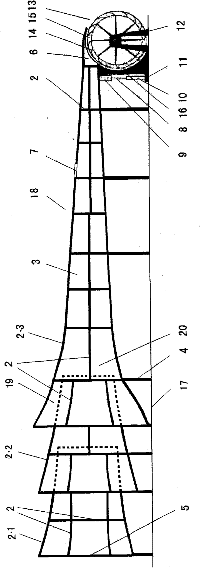
[0033] figure 1 Among them, 1 is a horizontal horn-mouth air gathering tube wind gathering wind wheel device, 2 is the skeleton of the wind gathering tube; 3 is a wall plate, which is fixed on the skeleton 2 to form the wind gathering tube; 4 is a column of the wind gathering tube, 5 6 is the air outlet of the air gathering tube, and the air gathering tube is provided with a vent. Air outlet, 7 is the door of air outlet; Open when not needing wind power and let out air. Air gathering cylinder is provided with damper 8,9 is the guide groove of damper 8, is provided with guide rail, makes damper 8 move switch up and down; During the lifting of the top column, the damper 8 rises (closes) or falls (opens) thereupon. 11 is the base of jack. A base 12 is established in front of the air outlet 6 , and the wind wheel 13 is fixed on the main shaft. One or both ends of the main shaft are provided with bearings, and the bearings are located on the base 12 . Windshields 14 are arrange...

Embodiment 2

[0037] The wind gathering wind wheel device can be provided with a plurality of bell mouths gathering wind. figure 2 It is a horizontal multi-air inlet wind gathering wind wheel device 18, which has three bell mouth gathering wind tubes interlaced (can be formed by more bell mouth gathering wind tubes), that is, a part of the wind gathering tube 2.1 air outlet is in the In the bell mouth of the air duct 2.2; a part of the air outlet of the air gathering tube 2.2 is in the bell mouth of the air gathering tube 2.3. In the staggered parts of the air gathering tubes, the annular interval 19 between them is that the air inlet is higher than the air outlet, or the annular interval 19 separates air ducts with large air inlets and small air outlets. 20 is polywind cavity. figure 2 Among them, the names of the icons 2 to 4, 6 to 17 are the same as those in the first embodiment.

[0038] This structure can increase the air intake volume of the air gathering tube, so that the wind th...

Embodiment 3

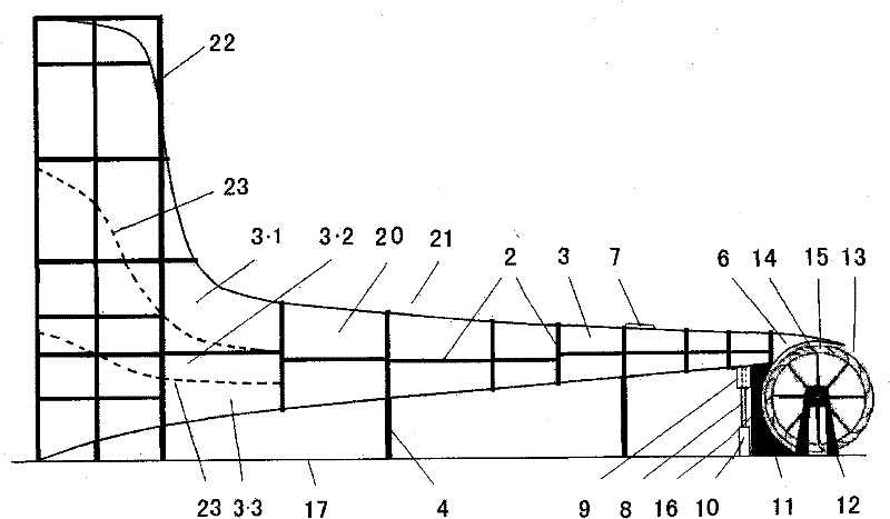
[0040] image 3 Among them, 21 is " L " shape multi-horn mouth wind gathering wind wheel device (" L " shape refers to the shape of the wind gathering wind wheel device gathering wind tube). The erected air-gathering tube of this wind-gathering wind wheel device establishes protective frame 22; Set partition 23 (dotted line is partition) in the erected wind-gathering tube, constitute air duct 3.1, 3.2 and 3.3 (can set More air passages), so that the air intake of air passage 3.1, 3.2 or 3.3 does not interfere with each other, and a certain wind force can be generated to enter the wind gathering chamber 20, and the wind force of the air outlet 6 is further enhanced. image 3 Among them, the names of the icons 2 to 4, 6 to 17 are the same as those in the first embodiment.


PUM


Abstract

The invention discloses a wind-collecting wind generation device. A vertical wind-collecting barrel of the L-shaped wind-collecting barrel is divided in to an upper layer and a lower layer. A wind inlet can rotate along with the wind direction for wind collection. The wind-collecting wind generation device has much wind collection direction. Surfaces and openings corresponding to the two layers of wind-collecting barrels are all arranged in a round shape. Wind-discharging proof mechanisms are arranged at interval. The collected wind has little loss. Each of the two layers of wind-collecting barrels is provided with a partition plate, which forms a wind channel. The wind is increased. The weak wind resources can be utilized so that the wind field resources can be fully used, and the construction is easy and the investment is less.

Description

(1) Technical field [0001] The invention relates to a wind power utilization device and a wind power generation device, in particular to a wind gathering wind wheel device and a wind gathering power generation equipment. (2) Background technology [0002] Existing existing multiple wind wheel device, as windmill, paddle type wind wheel etc. The places where various wind wheels are installed need a wind field with a certain wind speed, but the wind force of the wind field is often unstable, and there are weak wind seasons throughout the year, so the wind wheel cannot start or rotate very slowly, such as the blades used for power generation Type wind wheel just can't generate electricity or can only generate less electricity when the wind is weak. The existing wind rotor blades for power generation should generally have a wind speed of 3m / s or more to start generating electricity. However, the construction of this kind of wind farm has limited wind resources, long testing per...

Claims


Application Information

Patent Timeline
Patent Type & Authority Applications(China)
IPC IPC(8): F03D3/04F03D3/06F03D9/00F03D11/00
CPCY02E10/74Y02E10/72
Inventor 黄宝文黄郑隽
Owner 黄郑隽
Learn More