
Waste heat power generation system of multiple glass kilns

A glass kiln and waste heat power generation technology, which is applied in the control system, steam generation method using heat carrier, furnace, etc., can solve the problems of large fluctuation range of exhaust gas waste heat parameters, high one-time investment cost, and low waste heat utilization efficiency. Achieve the effects of reducing one-time construction investment, improving waste heat utilization rate, and improving power generation quality

Inactive Publication Date: 2011-11-16
南志远
View PDF1 Cites 12 Cited by
  • Summary
  • Abstract
  • Description
  • Claims
  • Application Information

AI Technical Summary

Problems solved by technology

[0004] The purpose of the present invention is to solve the problems of low waste heat utilization efficiency, low power generation efficiency, poor system stability, high heat recovery cost, large fluctuation range of waste gas heat parameters, serious environmental pollution, and one-time investment in the waste heat utilization of traditional glass kilns. High cost and other technical problems, in order to provide a multiple glass kiln waste heat power generation system with high waste heat utilization rate, high power generation efficiency, good system stability, low heat recovery cost, environmental protection, and investment cost saving

Method used


Image

  • Waste heat power generation system of multiple glass kilns
  • Waste heat power generation system of multiple glass kilns
  • Waste heat power generation system of multiple glass kilns

Examples


Embodiment Construction

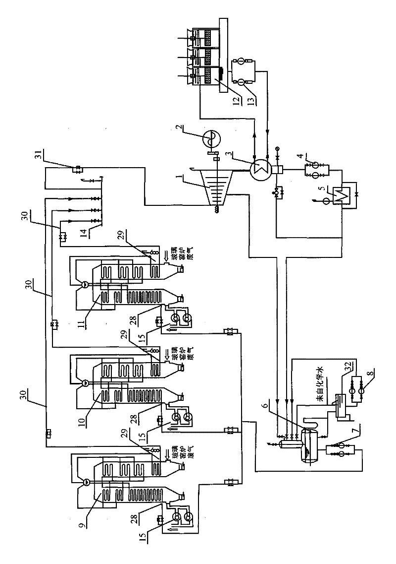
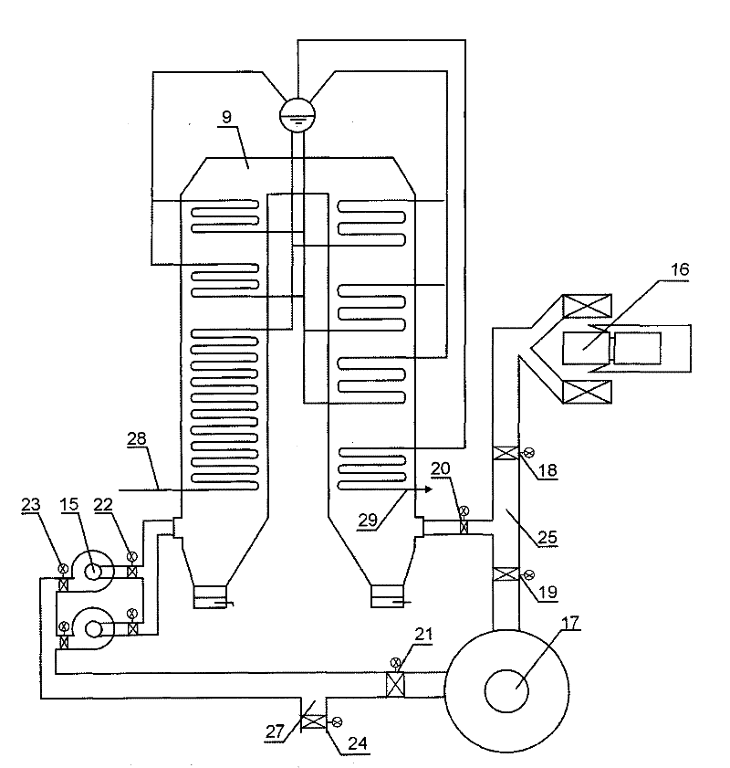
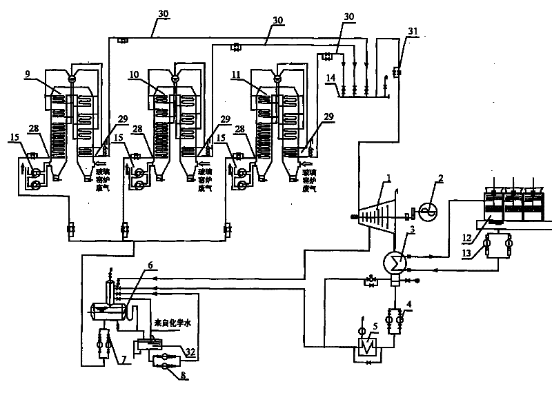
[0018] The detailed structure of the present invention, application principle, function and effect, refer to the appended figure 1 .2 Illustrate through the following implementation methods.

[0019]In the multiple glass kiln waste heat power generation system of the present invention, the flue gas outlets of multiple glass kilns 16 are in one-to-one correspondence with the flue gas inlets of multiple parallel waste heat boilers through the outlet flue 25, and the smoke of the waste heat boilers The gas outlet is connected to the chimney 17; the waste heat boiler is a single drum "Π" type waste heat boiler, that is, two vertical shaft flue gas channels are connected and arranged in a "Π" type. The water outlets of the boiler water pump 7 are respectively connected with the circulating water inlets 28 of multiple waste heat boilers, and the steam outlets 29 of multiple waste heat parallel boilers are connected with the steam collection cylinder 14 through the steam pipe 30, and...


PUM


Abstract

The invention relates to a waste heat power generation system of multiple glass kilns. The system solves the technical problems of low waste heat utilization efficiency, low power generation efficiency, poor system stability, high heat reclamation cost, large waste gas heat parameter fluctuation range, serious environmental pollution, high disposable investment cost and the like in the waste gas heat utilization of the traditional glass kilns. The smoke exhaust ports of the multiple glass kilns are communicated with the smoke inlets of multiple parallel waste heat boilers, and the smoke outlets of the waste heat boilers are communicated with a chimney; the water outlet end of a boiler water pump is communicated with the circulating water inlets of the multiple parallel waste heat boilers respectively, the steam outlets of the multiple parallel waste heat boilers are communicated with a steam collecting cylinder, the outlet of the steam collecting cylinder is communicated with the steam input port of a steam turbine, and the steam turbine is connected with a generator; and a steam discharge pipe of the steam turbine is connected with a condensed water system, and the condensed water system is communicated with the water inlet end of the boiler water pump through a deoxidation device. The system is suitable for waste heat power generation of two or more glass kilns.

Description

technical field [0001] The invention relates to waste heat utilization in the glass industry, in particular to a waste heat power generation system of multiple glass furnaces. Background technique [0002] We know that the exhaust gas discharged from the glass furnace is large, but the temperature is low, and the utilization rate is between 30% and 40%. There will be a large amount of residual energy, and most of the residual energy exists in the form of exhaust heat. If the exhaust gas waste heat resources are not fully recycled, not only waste heat energy will be wasted, but also pollute the environment and destroy nature. [0003] Glass kilns in the glass industry usually use heavy oil, natural gas, coal gas, etc. as fuel, and the flue gas formed by the combustion of fuel in the furnace is discharged outside the kiln, which generates waste gas and waste heat resources. The exhaust gas of the glass kiln belongs to the waste heat of the medium-temperature exhaust gas, the ...

Claims


Application Information

Patent Timeline
IPC IPC(8): F01K11/02F01K13/00F01D15/10F22B1/18F27D17/00F22D11/06F22B35/00
CPCY02P10/25
Inventor 南志远
Owner 南志远
Learn More