Dehydration method for desorption gas used in desulphurization of flue gas

A desorption and gas technology, applied in separation methods, chemical instruments and methods, sulfur compounds, etc., can solve the problems of dilution of desulfurization solution, reduction of energy consumption for desorption, and increase of energy consumption for desulfurization

Inactive Publication Date: 2011-11-23
PANZHIHUA IRON AND STEEL +2
View PDF7 Cites 8 Cited by
  • Summary
  • Abstract
  • Description
  • Claims
  • Application Information

AI Technical Summary

Problems solved by technology

[0005] The patent application with the publication number CN200920350778.X discloses a desorption system, which mainly regenerates the desulfurization solution twice, and returns the condensate of the regenerated high-temperature gas to the desorption system (that is, the desorption system). The sulfur dioxide gas is heated, and the desorption energy consumption of the desulfurized rich solution will be reduced, but the desulfurization solution will still be diluted during the circulation process.
In addition, the existing organic amine desulfurization technology is to perform one-stage absorption and one-stage desorption. The condensate of the desorbed gas is directly returned to the desorption system. It takes a lot of heat for the condensate to rise from about 50°C to the desorption temperature. The degree of desorption of rich liquid increases the energy consumption of desorption
[0006] In the above patent application, in the flue gas washing process, the desulfurization system is difficult to maintain the water balance due to the moisture content of the flue gas, the demisting of the upper layer of the washing section, and the exhaust gas of the flue gas after washing, which will cause the solution to become diluted
At the same time, the condensed water in the desorbed high-temperature gas is returned to the desorption system, which does not effectively reduce the amount of water in the desorbed gas, thereby increasing the desulfurization energy consumption
[0007] In order to overcome the disadvantages of the increase of water in the existing flue gas desulfurization solution and the high desorption energy consumption of the desulfurization and desorption condensate returned to the desorption system, a separate treatment of the gas condensate in the desorption system is needed, so as to solve the problem of increased water volume and high energy consumption in the system And other issues

Method used


Image

  • Dehydration method for desorption gas used in desulphurization of flue gas
  • Dehydration method for desorption gas used in desulphurization of flue gas
  • Dehydration method for desorption gas used in desulphurization of flue gas

Examples


Embodiment 1

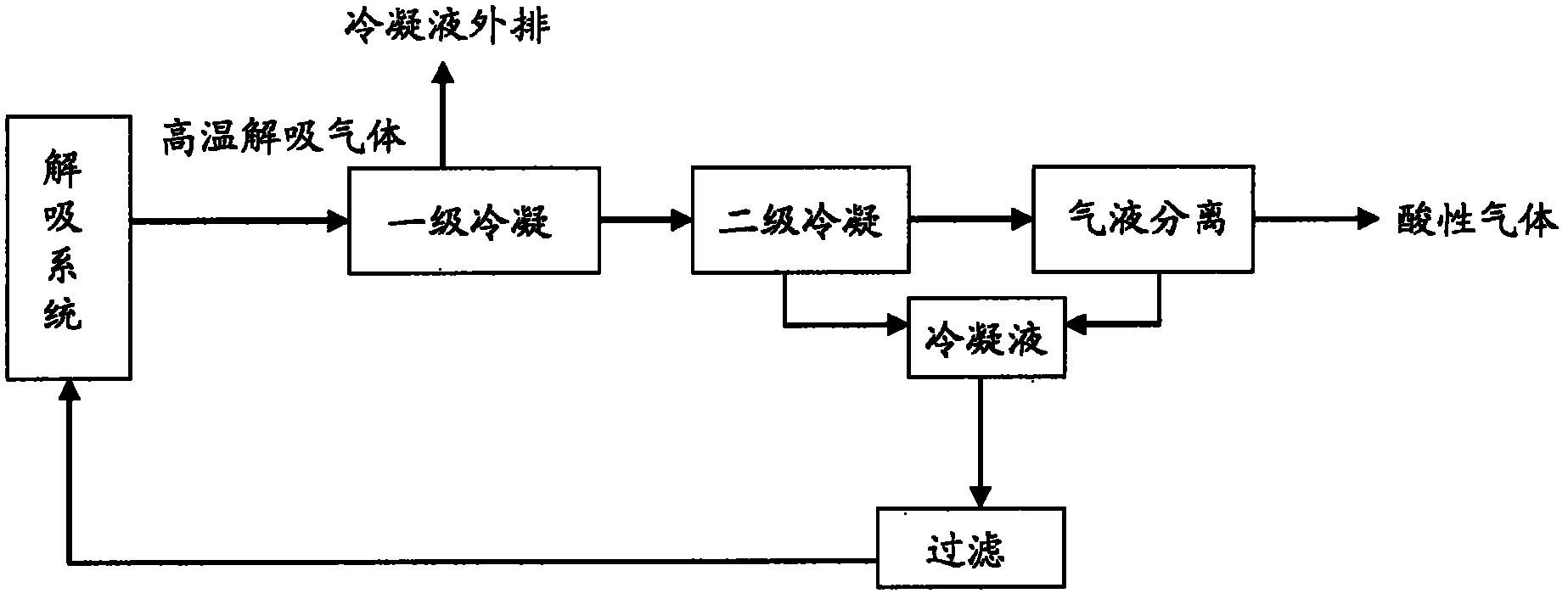
[0026] refer to figure 1 , In this embodiment, the high-temperature desorption gas desorbed from the desorption system is subjected to two-stage condensation. The first condensate produced by the primary condensation is directly discharged, and the first condensate mainly contains water and a small amount of sulfurous acid. Then the desorption gas mainly containing desulfurizing agent, water and impurities produced by the primary condensation is subjected to secondary condensation to produce a second condensate and desorption gas. The second condensate is a saturated sulfurous acid solution and contains a small amount of desulfurizing agent and impurities ( Such as sulfur, etc.).

[0027] Subsequently, the desorbed gas is supplied to a gas-liquid separation device for gas-liquid separation, thereby generating sulfur dioxide-containing acid gas and liquid. The liquid produced by gas-liquid separation mainly contains water, and contains a large amount of sulfur dioxide and imp...

Embodiment 2

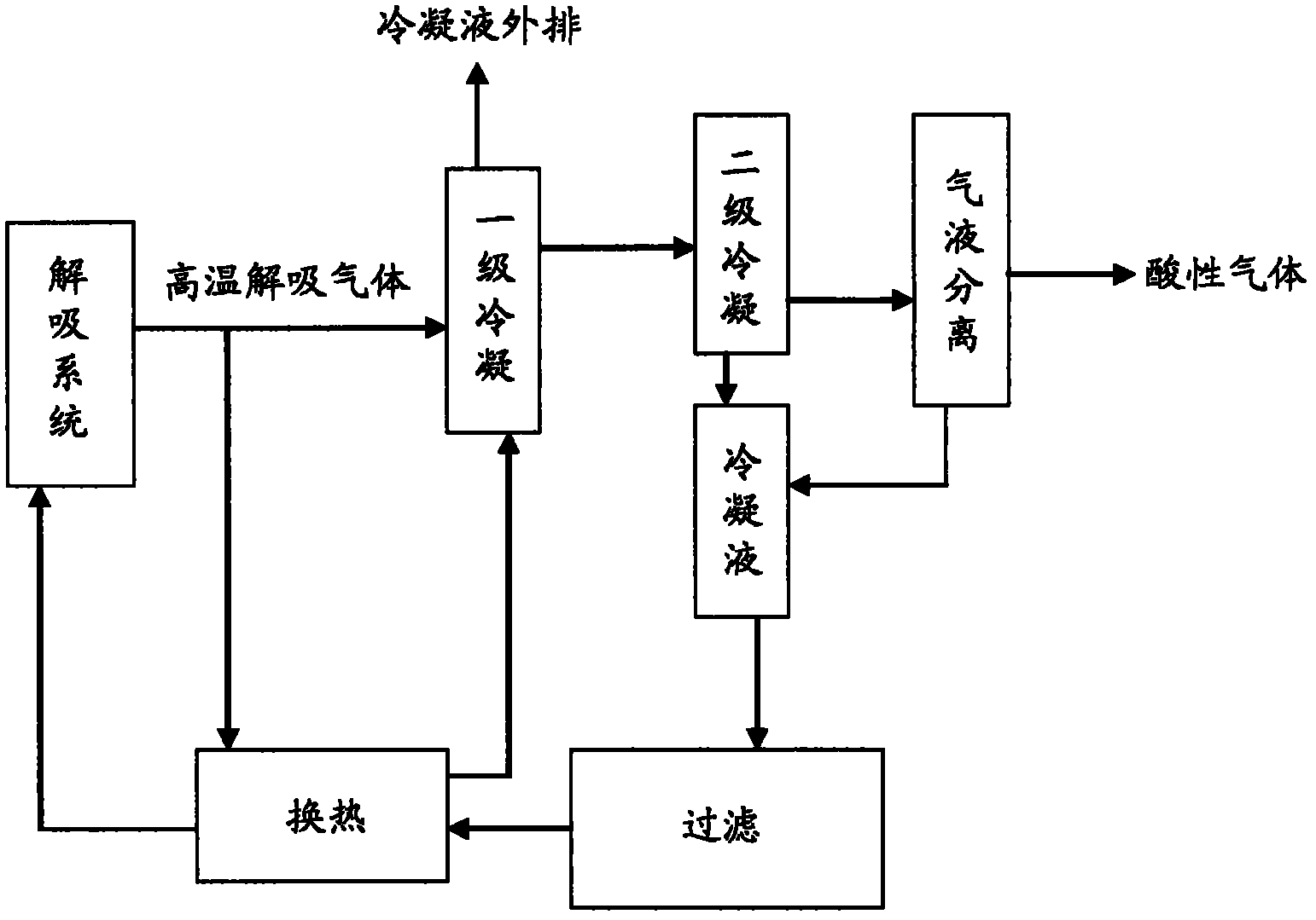
[0031] refer to figure 2 , in this embodiment, in addition to including the steps in Embodiment 1, the method of this embodiment also includes the following steps: before providing the filtered desulfurization liquid into the desorption system, making the desulfurization solution The thermal system exchanges heat with a part of the desorbed gas desorbed from the desorption system, then supplies the desulfurization solution after heat exchange to the desorption system, and makes the part of the desorbed gas after heat exchange go through steps such as primary condensation.

Embodiment 3

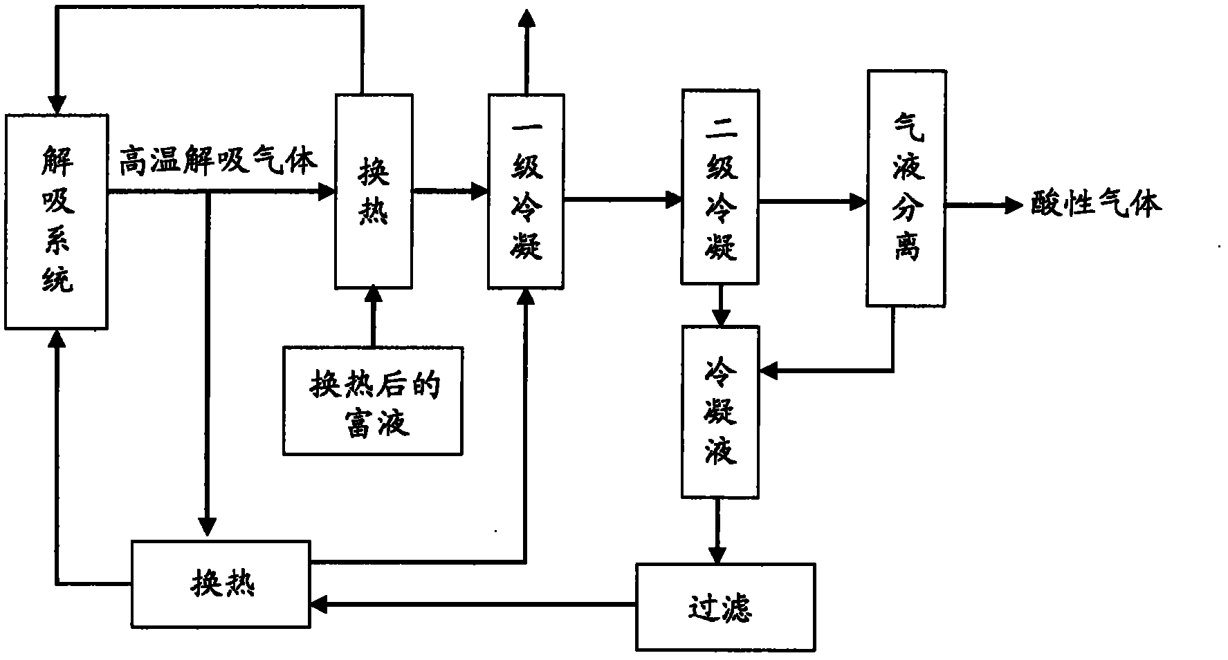
[0033] refer to image 3 , in this embodiment, in addition to including the steps in Embodiment 2, the method of this embodiment also includes the following steps: make another part of the desorbed gas desorbed from the desorption system exchange heat with the second heat exchange system After heat exchange, the rich liquid after heat exchange is then supplied to the desorption system, and the other part of the desorbed gas after heat exchange is subjected to steps such as primary condensation. In this embodiment, the rich liquid after heat exchange is the rich liquid that has absorbed sulfur dioxide after heat exchange with the high-temperature lean liquid from the desorption system from the absorption tower. Specifically, the temperature of the rich liquid that has absorbed sulfur dioxide in the absorption tower is 45-55°C, and the temperature of the high-temperature lean liquid discharged from the bottom of the desorption system is 100-115°C. After the heat exchange of the...


PUM


Abstract

The invention provides a dehydration method for desorption gas used in desulphurization of flue gas. The method comprises the following steps: carrying out primary condensation and secondary condensation on desorption gas which has been desorbed from a desorption system so as to obtain first condensate liquid, second condensate liquid and desorption gas containing vapor, sulfur dioxide gas and a desulfurizer; delivering the resultant desorption gas into a gas-liquid separation device for gas-liquid separation so as to generate liquid and acidic gas containing sulfur dioxide; delivering the resultant second condensate liquid and liquid generated in gas-liquid separation into a suspension filter for filtration so as to remove impurities in the liquid and obtain a desulphurization solution containing saturated sulfurous acid and a small amount of desulfurizer; supplying the desorption system with the desulphurization solution. The method provided in the invention can effectively maintain water balance of the desorption system, utmostly reduces loss of sulfur dioxide, and further reduces energy consumption and the like of the desorption system.

Description

technical field [0001] The invention relates to a method for dehydrating flue gas desulfurization and desorption gas, in particular to a method for removing moisture from flue gas desulfurization and desorption gas. Background technique [0002] Sulfur dioxide seriously pollutes the environment. It is necessary to use a desulfurization solution containing a desulfurizer to absorb sulfur dioxide, and then to desorb the desulfurization solution rich in sulfur dioxide, so that the desulfurization solution desorbed from sulfur dioxide can be reused. Sintering flue gas of steam and sulfur dioxide and a part of desulfurization agent. Traditionally, the desorption gas contains a large amount of water vapor, and the discharged desorption gas is condensed. On the one hand, the desorption gas mainly containing sulfur dioxide is obtained, and on the other hand, the condensed condensate containing a large amount of water is supplied to the desorption device again. In addition, the sint...

Claims


Application Information

Patent Timeline
Patent Type & Authority Applications(China)
IPC IPC(8): B01D53/14B01D5/00C01B17/56
Inventor 张初永邱正秋刘燕川刘潘赵磊
Owner PANZHIHUA IRON AND STEEL
Why Eureka
Try Eureka