Silicon-cup energy-accumulation Al/CuO composite film ignition bridge and ignition bridge array

A composite film and ignition bridge technology, applied in fuzes, offensive equipment, etc., can solve problems such as low energy conversion rate, and achieve the effect of enhancing ignition capability, improving integration, and improving the ability to prevent radio frequency.

Inactive Publication Date: 2011-11-23
NANJING UNIV OF SCI & TECH
View PDF5 Cites 10 Cited by
  • Summary
  • Abstract
  • Description
  • Claims
  • Application Information

AI Technical Summary

Problems solved by technology

The thin-film bridge can be manufactured by MEMS technology, and it is easy to realize the integrated production with other parts of the pyrotechnic device. However

Method used


Image

  • Silicon-cup energy-accumulation Al/CuO composite film ignition bridge and ignition bridge array
  • Silicon-cup energy-accumulation Al/CuO composite film ignition bridge and ignition bridge array
  • Silicon-cup energy-accumulation Al/CuO composite film ignition bridge and ignition bridge array

Examples


Embodiment 1

[0041] Ignition bridge of single silicon cup concentrated Al / CuO composite thin film

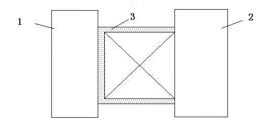
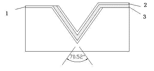
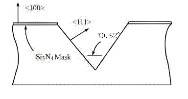
[0042] Fabrication of Si on a 100-sided silicon substrate 3 N 4 mask, which is etched using anisotropic etching technology of silicon such as figure 2 The silicon cup of the regular square pyramid structure shown has a side length of 1mm. The corrosion conditions are: 5% mass concentration of TMAH (tetramethyl ammonium hydroxide) corrosion solution, the corrosion temperature is 85 ℃, when the predetermined depth is reached, use 20% TMAH solution + 1% AP (ammonium perchlorate) , the temperature is 85 ℃, the time is half an hour, and the modification is carried out to reduce the roughness.

[0043] The ignition bridge processing process is as follows: ultrasonically clean the substrate with acetone and deionized water for 30 minutes, dry it in the air, and then put it into a 200°C oven to bake for later use. A positive reversal photoresist (AZ5200) was used to coat the substrate and then ...

Embodiment 2

[0046] Ignition Array Based on Silicon Cup Concentrated Al / CuO Composite Thin Film Ignition Bridge as the Basic Unit

[0047] The silicon cup energy-gathering Al / CuO composite thin film ignition bridge arrays are all fabricated by microfabrication technology, and a micro ignition array can be fabricated based on the single ignition bridge described in Example 1. The structure of the ignition array is as Figure 5 shown.

[0048] Figure 5 The black part is the ignition bridge, which constitutes 6×6 ignition units. The independent ignition of the ignition unit can be realized through the logic addressing circuit between the ignition bus and the unit. The logic addressing circuit material adopts Cu or Au thin film. Cu or Au thin film has lower resistivity and less influence on the ignition bridge, and the width of the circuit is 50μm. Similar to this logic-addressed ignition circuit, it can be used for the ignition of micro-propeller systems, as well as for multi-point igniti...


PUM


Abstract

The invention discloses a silicon-cup energy-accumulation Al/CuO composite film ignition bridge and an ignition bridge array. A silicon cup with equilateral tetragonal pyramid slopes is made on a silicon chip by an anisotropic etching technique. The ignition bridge is formed by superposing an upper electrode, a lower electrode and a dielectric layer, wherein two metal films with the same size in opposite directions are respectively used as the upper electrode and the lower electrode, and an Al/CuO composite film layer which has the same size and direction as the upper electrode metal film is sandwiched between the two metal films as the dielectric layer; the Al/CuO composite film layer is partially covered and superposed on the lower electrode metal film, and the upper electrode metal film is completely covered and superposed on the Al/CuO composite film layer; and an Au metal film or Cu metal film is made into a lead for connecting a plurality of silicon-cup energy-accumulation Al/CuO composite film ignition bridges, so that the silicon-cup energy-accumulation Al/CuO composite film ignition bridges are arranged to form an ignition array. The invention has the functions of high self anti-RF capability, strong ignition capability, and favorable integration level with other components of the initiating explosive device.

Description

[0001] technical field [0002] The invention belongs to the field of basic components of electrical firework products, in particular to an ignition bridge and an ignition bridge array of a silicon cup energy-gathering Al / CuO composite thin film. Background technique [0003] Electrical explosives are one of the most commonly used initial energy sources for the combustion and explosion of energetic materials. They are widely used in weapons and equipment and the national economy, such as mine blasting, safety protection airbags, micro-satellite propulsion systems, rocket engine ignition systems, combat The fire and detonation sequences of the Ministry, the ballistic correction of the missile and the safety and security devices, etc. [0004] The bridge-wire type electrical thermal power product is the most widely used electrical thermal power product. It relies on the electric current to pass through a fine metal bridge wire with a certain resistance, and the electric energ...

Claims


Application Information

Patent Timeline
IPC IPC(8): C06C5/00
Inventor 朱朋沈瑞琪叶迎华胡艳吴立志周翔
Owner NANJING UNIV OF SCI & TECH
Why Eureka
Try Eureka