Eureka AIR delivers breakthrough ideas for toughest innovation challenges, trusted by R&D personnel around the world.

Energy-saving boiler special for combustion test stand

A combustion test and boiler technology, which is applied in the direction of combustion method, furnace, furnace type, etc., can solve the problems of combustion chamber structure, shape burner mismatch, unsatisfactory combustion effect, poor energy saving and environmental protection, and achieve compact structure, Light weight, good sealing effect

Active Publication Date: 2011-11-23
JIANGSU SIFANG BOILER +1
View PDF5 Cites 2 Cited by
  • Summary
  • Abstract
  • Description
  • Claims
  • Application Information

AI Technical Summary

Problems solved by technology

If the existing general boiler is directly used to test the newly developed burner, there are the following deficiencies: first, it is difficult to meet the requirements of both oil burner and coal burner at the same time; The structure and shape of the combustion chamber of the permanent boiler do not match the developed burner, which will lead to unsatisfactory combustion effect; the third is that the energy saving and environmental protection are not good
In addition, when the burner is tested, the temperature of the exhaust gas is as high as several 100°C. If it is directly discharged into the atmosphere, it is not only unsafe, but also a waste of energy. At the same time, the air preheating required by the burner has to be added An auxiliary heating device to increase energy consumption

Method used


Image

  • Energy-saving boiler special for combustion test stand
  • Energy-saving boiler special for combustion test stand
  • Energy-saving boiler special for combustion test stand

Examples


Embodiment Construction

[0016] An embodiment of the present invention will be further described below in conjunction with accompanying drawing:

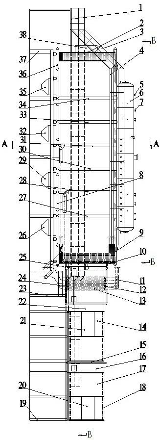
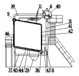
[0017] figure 1 As shown, the energy-saving boiler dedicated to the combustion test bench of the present invention is mainly composed of a combustion chamber, a drum 6, an evaporator, an air preheater, and a support frame assembly. The combustion chamber consists of front and rear furnace walls 2 and 10 parallel to each other, and is located between the front and rear furnace walls 2 and 10 in a box body surrounded by an L-shaped upper right furnace wall 42 and an L-shaped left lower furnace wall 46 interlocked with each other. The L-shaped upper right furnace wall 42 is a pipe-laying furnace wall, and its inner surface is provided with a right upper membrane water-cooled wall 41; the L-shaped left lower furnace wall 46 is a tube-laying furnace wall, and its inner surface is provided with a left lower membrane water-cooled wall 45; The upper and lower ends...


PUM


Abstract

The invention discloses an energy-saving boiler special for a combustion test stand. The energy-saving boiler special for the combustion test stand mainly comprises a combustion chamber, a boiler barrel, an evaporimeter, an air preheater, and a support frame assembly. The evaporimeter is distributed at the outlet of the combustion chamber; the air preheater is distributed on the rear part of the evaporimeter in a horizontal mode; an expansion joint is arranged between the evaporimeter and the combustion chamber and between the evaporimeter and the air preheater; the outlet of the evaporimeteris provided with a manhole for overhauling; a refractory belt with an adjustable area is arranged on the front half part of the bottom of the combustion chamber; the bottom of the combustion chamber is provided with a plurality of slag holes and ash buckets along the longitudinal direction; a cooling section pipe box of the air preheater is provided with two cold air ports and can adapt to an oilcombustor and a coal combustor simultaneously; by a membrane water cooled wall, the boiler wall thickness of the combustion chamber and the weight of the combustion chamber are greatly reduced, and the combustion chamber has high tightness and is not easy to slag; the evaporimeter is arranged, so that heat of the discharged smoke can be fully used, and the temperature of the discharged smoke is greatly reduced; and by using a spiral grooved tube, the flowing smoke is subjected to strong turbulence and perturbance, the heat exchange is enhanced, the temperature of the discharged smoke is effectively reduced, the combustion in the boiler is enhanced, and the economy of the combustion is improved.

Description

technical field [0001] The invention relates to a special boiler, in particular to a special energy-saving boiler suitable for a combustion test bench of an oil burner or a coal burner. Background technique [0002] In order to deeply understand and master or check the combustion characteristics of the oil burner and coal burner developed by a certain combustion control company and their influence on the boiler structure, it is very necessary to conduct experimental research on them. If the existing general boiler is directly used to test the newly developed burner, there are the following deficiencies: first, it is difficult to meet the requirements of both oil burner and coal burner at the same time; The structure and shape of the combustion chamber of the permanent boiler do not match the developed burner, which will lead to unsatisfactory combustion effect; the third is that the energy saving and environmental protection are not good. In addition, when the burne...

Claims


Application Information

Patent Timeline
Patent Type & Authority Applications(China)
IPC IPC(8): F27B17/02F23L15/00
CPCY02E20/34
Inventor 段绪强常春梅闫海州刘凤彭玉兴谢传玉耿平平
Owner JIANGSU SIFANG BOILER
Why Eureka
Eureka Blog
Learn More